


NTI NODEMUX SERIES UNIVERSAL KVM SWITCH
11
NOTES:
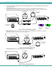
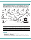
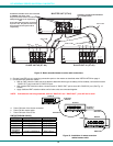
• Port 1 of the Master Unit with Slave Unit #1 connected to it will function and be controlled as ports 1-4 for an ST-
4U (1-8 for an ST-8U, etc.)
• Master Unit Port 2 with Slave Unit #2 connected will function and be controlled as the next sequential port
numbers (5-8 for an ST-4U, 9-16 for an ST-8U, etc.).
• Consecutive ports on the master used for locally connected CPU’s will function and be controlled as the next
consecutive port number. (I.e. Ports 3 and 4 of a 4-port master with only two 4-port slaves connected will
function and be controlled as ports 9 and 10 respectively.) See Fig. 15 on page 12 for an illustration of this.
f. All units must be powered OFF during configuration and interconnecting.
g. For multi-platform cascaded systems (systems with MAC, SUN, and/or PS/2 CPUs mixed together), each slave unit is “uni-
platform” - that is, slaves can only have CPUs of the same platform connected to them and the cable between the slave and
master unit must support that platform.
h. Cascading is not available if the Touch-Screen Support option (page 25) is installed.
Configuration
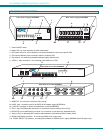
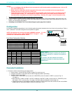
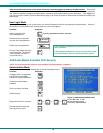
All units are configured using switches 1 thru 6 of the 8-position dip-switch (located on the front of each unit) according to Tables 1
and 2. (Switches 7 and 8 are configured for the keyboard on page 5.)
NOTE: Dip-switches are only found in legacy NODEMUX switches. If no dip-
switches are present, refer to "Switch Configuration" on page 17. Then
continue with "Cascaded Installation" below.
Front Panel Configuration Switches
Table 1 * (default settings)
Switch 1 5 6
STAND-ALONE SWITCH OFF* OFF* OFF*
SLAVE ON OFF OFF
MASTER W/4-PORT SLAVES OFF OFF ON
MASTER W/8-PORT SLAVES OFF ON OFF
MASTER W/16-PORT SLAVES OFF ON ON
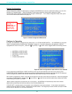
Table 2 * (default settings) Master & Slave dip-switch 2-4 Settings
2 3 4 Master with- Slave Setting
OFF* OFF* OFF* No Slave Attached N/A
OFF OFF OFF 1 Slave attached Slave Unit #1
OFF OFF ON 2 Slaves attached Slave Unit #2
OFF ON OFF 3 Slaves attached Slave Unit #3
OFF ON ON 4 Slaves attached Slave Unit #4
ON OFF OFF 5 Slaves attached Slave Unit #5
ON OFF ON 6 Slaves attached Slave Unit #6
ON ON OFF 7 Slaves attached Slave Unit #7
ON ON ON 8 Slaves attached Slave Unit #8
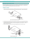
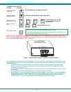
Cascaded Installation
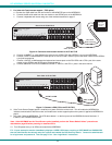
a. Connect all slaves consecutively to the master switch.
• Perform steps 1-3 under INSTALLATION (on page 5) for each slave unit.
• Configure each switch as per tables above under Configuration before proceeding.
• Attach the slaves to the master:
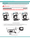
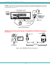
• With a VEXT-xx-MM cable, connect slave #1’s “MONITOR” port to the master’s “VIDEO 1” port (see Fig. 15
on page 11).
• With an SKTINT-xx-MM or VKTINT-1/VKTINT-xx-MM pair or MKTINT-xx-MM, connect slave #1’s “DEVICES” port to
the master’s “CPU 1” port (see Fig. 15 on page 12 and the cables and adapters chart on page 10).
• Repeat these steps for each additional slave unit, keeping in mind that each slave will connect into the next available
master’s port (i.e. slave #2 to master’s “VIDEO 2” and “CPU 2”, etc.).
A
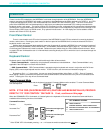
bout Table 2:
These switch settings are used by the slave(s) to
establish its identity (i.e. location in the group) to
the master.
In a master, the same switches are used to
configure the master for how many slaves are
attached to it.
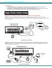
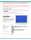
8-POSITION
DIP-SWITCH
1
2345678
Scan
Com mandBroad cast
1 8
ON
NTI
R
Network Technologies Inc
ON
OFF
1 2 3 4 5 6 7 8