


NTI NODEMUX SERIES UNIVERSAL KVM SWITCH
33
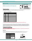
Keyboard Replacement
Should it be necessary to replace the keyboard of one platform with a keyboard of a different platform, the dip-switches will need
to be re-configured accordingly. To do this;
1. Power-down the ST-xU by following the proper power-down sequence. That is, turn the CPUs OFF first, then the NTI
switch.
2. Replace the keyboard.
3. Re-configure the switches (see Fig. 3 on page 5.) and then power up, following the proper power-up sequence. That is,
turn ON power to the NODEMUX first, then to the CPUs.
Note: If the keyboard is being replaced with one from the SAME PLATFORM, it can be hot-swapped without powering-
down.
FYI: This procedure applies to legacy NODEMUX switches only. If not a legacy NODEMUX, to change the keyboard
configuration from one platform to another, simply unplug the old keyboard, plug in the new keyboard, and power cycle
the NODEMUX once.
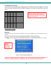
HOW TO DISABLE OPERATING MODES
NOTE: This section only applies to legacy NODEMUX switches. If the NODEMUX does not have dip switches for RS232
control (page 27) but has a DB-9 RS232 port, this section DOES NOT APPLY.
Three operating modes of the NODEMUX can be disabled if a user desires to do so. The Command Mode can be disabled
which would also disable the Scan and Broadcast Modes, or, the Scan and/or Broadcast Modes can be individually disabled
leaving the other features in Command Mode enabled.
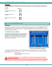
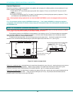
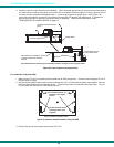
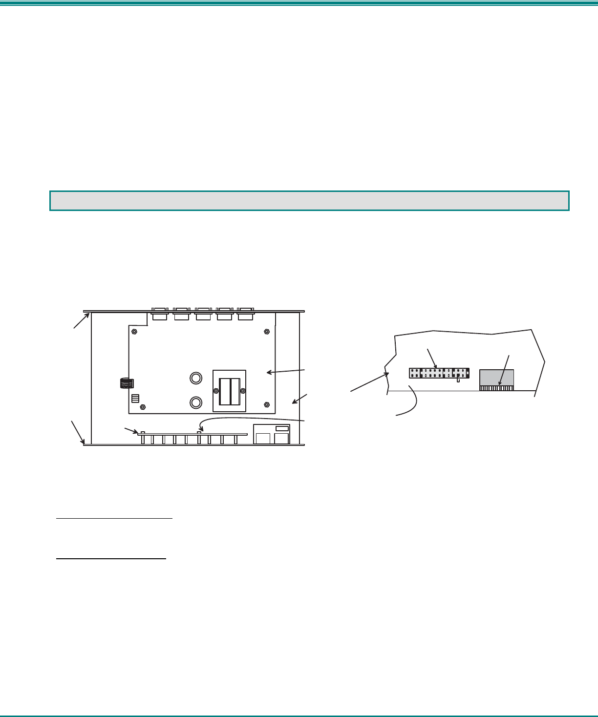
To disable these operating modes, the user must get access to the jumper block. This block is located close to the dip-
switches on the circuit board the keyboards plug into (called the digital board) inside the ST-xU. (See Fig. 36.)
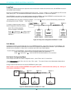
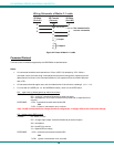
Figure 36- Location of jumper block
If the unit is a rackmount style, the digital board is located directly beneath the cover of the unit, requiring the user to only remove
the 9 screws from the cover to get access. With the cover removed, the jumper block will be easy to locate (see Fig. 36).
Follow the instructions under "CONFIGURING THE JUMPER BLOCK" (pg. 37) to disable the desired mode(s).
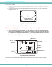
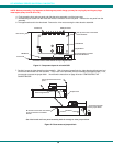
If the unit is in a plastic case, the digital board is located on the bottom of the case, requiring the user to partially disassemble the
unit to gain access to the jumper block. If the unit has the OSD option (ST-xU-O), the procedure will be different than the
procedure used if the unit does not have the OSD option.
V i d e o B o a r d
D i g i t a l B o a r d
O v e r h e a d v i e w o f v i d e o b o a r d o n t o p o f d i g i t a l b o a r d .
T h e j u m p e r b l o c k i s l o c a t e d
b e l o w t h e L E D b o a r d .
R e a r P a n e l
F r o n t P a n e l
L
C
D
E
K
C
M
D
B
R
D
C
S
C
A
N
J U M P E R B L O C K
D I P S W I T C H E S
L E D b o a r d
C l o s e u p v i e w o f j u m p e r b l o c k o n d i g i t a l b o a r d .