


iii
MAN064 Rev Date11/10/2005
TABLE OF FIGURES
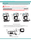
Figure 1- Secure rackmount ears to switch........................................................................................................................................4
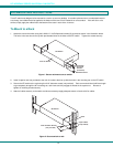
Figure 2- Secure switch to rack .........................................................................................................................................................4
Figure 3- Dip-switch configuration .....................................................................................................................................................5
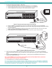
Figure 4- Connect the monitor ...........................................................................................................................................................5
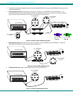
Figure 5- Connect a PS/2 keyboard and mouse................................................................................................................................6
Figure 6- Connect a MAC keyboard/mouse.......................................................................................................................................6
Figure 7- Connect a SUN keyboard/mouse .......................................................................................................................................6
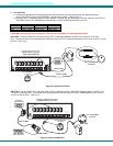
Figure 8- Connect a PS/2 CPU..........................................................................................................................................................7
Figure 9- Connect a MAC CPU..........................................................................................................................................................7
Figure 10- Connect a SUN CPU........................................................................................................................................................8
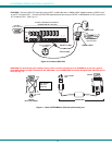
Figure 11- Use a VOPEX-IM9D for CPU with serial mouse port........................................................................................................8
Figure 12- Connect a touch-screen monitor to an ST-8U-TS-R.........................................................................................................9
Figure 13- Connect a PS/2 CPU to an ST-8U-TS-R..........................................................................................................................9
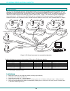
Figure 14- ST-8U used as a master in a cascaded configuration ....................................................................................................10
Figure 15- Basic cascaded master-to-slave cable connections .......................................................................................................12
Figure 16- Installation of remote extension......................................................................................................................................12
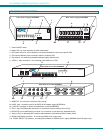
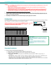
Figure 17- Video and Device connections identified with port numbers...........................................................................................14
Figure 18- Administration Mode menu.............................................................................................................................................16
Figure 19- Switch Configuration Mode screen.................................................................................................................................17
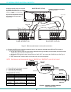
Figure 20- Switch configured as a master with one slave attached .................................................................................................17
Figure 21- Administrator password change .....................................................................................................................................18
Figure 22- Command Mode menus .................................................................................................................................................20
Figure 23- Video and Device connections identified with port numbers...........................................................................................21
Figure 24- Edit Mode .......................................................................................................................................................................22
Figure 25- Search Mode ..................................................................................................................................................................23
Figure 26- Maintenance Mode....................................................................................................
.....................................................24
Figure 27- Command Mode-Touch Enabled....................................................................................................................................25
Figure 28- Touch Maintenance Mode ..............................................................................................................................................26
Figure 29- Cursor Alignment menu..................................................................................................................................................26
Figure 30- RS232 dip switches........................................................................................................................................................27
Figure 31- Switch Configuration Mode screen.................................................................................................................................28
Figure 32- Daisy chain configuration with Matrix-Y-1 cable .............................................................................................................29
Figure 33- RS232 connection with Matrix-Y-1 cable........................................................................................................................29
Figure 34- Pinout of Matrix-Y-1 cable ..............................................................................................................................................30
Figure 35- Keyboard key layouts .....................................................................................................................................................32
Figure 36- Location of jumper block.................................................................................................................................................33
Figure 37- Case screws must be removed ......................................................................................................................................34
Figure 38- Component layout inside case........................................................................................................................................34
Figure 39- Clear access to the jumper block....................................................................................................................................35
Figure 40- Remove standoff screws in unit with OSD......................................................................................................................35
Figure 41- Component layout in unit with OSD................................................................................................................................36
Figure 42- Clear access to jumper block..........................................................................................................................................36
Figure 43- Configure the jumper block.............................................................................................................................................37
Figure 44- Support present for touch screen monitor on ST-8U-TS-R.............................................................................................37