


NTI NODEMUX SERIES UNIVERSAL KVM SWITCH
34
For models ST-xU (no OSD):
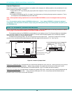
1. Make sure the ST-xU is completely disconnected from all CPU components. Be sure to unplug the ST-xU from the
electrical outlet.
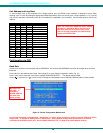
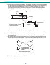
2. Remove the two philips-head screws from the underside of the ST-xU and set the ST-xU on a firm and flat surface,
bottom down (see Fig. 37).
Figure 37- Case screws must be removed
3. Remove the top half of the plastic case from the ST-xU.
NOTE: Before proceeding, it is important to discharge any static charge you may be carrying by touching any large
metal object (away from the ST-xU).
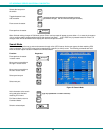
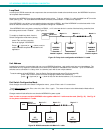
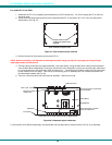
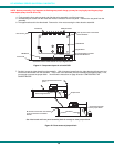
4. The first visible circuit board, the uppermost board, is the video board. Along the back of the video board are between
3 and 5 video ribbons (depending on how many monitors the unit is designed to connect to) connecting the video board
to a circuit board on the rear panel with 15HD connectors on it. Disconnect the flat ribbon cables from the video board
to each header on the rear panel. Take note as to where they go for re-assembly later. Do not disconnect them from
the video board headers (see Fig. 38).
5. There are 4 nuts that secure the video board to standoffs. Remove the 4 nuts.
Figure 38- Component layout inside case
To avoid further more difficult disassembly, the video board and front panel will be removed from the ST-xU as an assembly.
P h i l i p s - h e a d s c r e w s
h o l d i n g t h e p l a s t i c c a s e
t o g e t h e r
V i e w o f b o t t o m o f p l a s t i c c a s e
D i s c o n n e c t v i d e o
r i b b o n s h e r e
N u t s ( 4 ) s e c u r e t h e c i r c u i t b o a r d
t o t h e s t a n d o f f s .
V i d e o B o a r d
D i g i t a l B o a r d
1 5 H D C o n n e c t o r
O v e r h e a d v i e w o f v i d e o b o a r d o n t o p o f d i g i t a l b o a r d .
T h e j u m p e r b l o c k i s l o c a t e d
b e l o w t h e L E D b o a r d .
L E D B o a r d
F r o n t P a n e l
R e a r P a n e l