


NTI RACK MOUNT CONSOLE TERMINAL WITH CONSOLE SWITCH
6
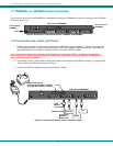
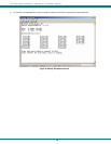
1.2 TERMINAL vs. SERIMUX Cable Connections
The connectors on the rear of the RACKMUX are split between those for the TERMINAL connections, and those for the SERIMUX
connections (see Fig. 2).
Figure 2- Distinction of connections between TERMINAL and SERIMUX
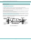
1.3 Connect Devices, Hosts, and Power
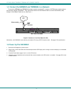
1. Connect each serial device or host to be connected by the SERIMUX to any port labeled "1" through "16" using a DTE
or DCE type serial cable. It may be necessary to add one of the cable adapters (supplied) detailed in "Cable Adapters"
(page 95) between the device port on the serial device or host and the RJ45 connector.
Note: There are two types of serial devices, data communication equipment (DCE)(i.e. modem) and data terminal
equipment (DTE) (i.e. CPU), each having different connector pin assignments. The cable adapters (see Materials on
page 3) make the proper connections.
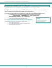
2. If connecting a printer, connect either a serial printer cable to the remaining male SUB D 9 connector or a parallel printer
cable to the female SUB D 25 connector (see Fig. 3).
3. Connect the 12VDC AC adapter to the power jack labeled "12VDC".
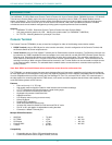
Figure 3- Connect serial devices, printer, and power supply
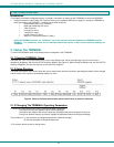
-
+
12VDC
ETHERNE SERIAL
PARALLEL
12345678
+
+
Rear View of RACKMUX
Console Terminal
(TERMINAL)
Console Switch
(SERIMUX)
910111213141516
+
RESET
12 VDC
AC
ADAPTER
Rear View of RACKMUX
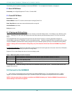
SERVER
ROUTER
FIREWALL
RJ45
Male
Connector
Ethernet cable
-
+
12VDC
ETHERNE
SERIAL
PARALLEL
12345678
+
+
910111213141516
+
RESET
Attach local printer
either by serial cable to "Serial"
or by parallel cable to "Parallel"
PBX