


iv
MAN081 Rev Date 2/7/2007
TABLE OF FIGURES
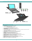
Figure 1- Mount RACKMUX to rack...................................................................................................................................................5
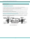
Figure 2- Distinction of connections between TERMINAL and SERIMUX .........................................................................................6
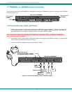
Figure 3- Connect serial devices, printer, and power supply .............................................................................................................6
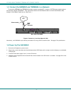
Figure 4- Connect to a Local Area Network (LAN).............................................................................................................................7
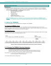
Figure 5- Fields in the Setup menu display which function keys to press for submenus ...................................................................8
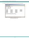
Figure 6- Startup- Accessible host list .............................................................................................................................................10
Figure 7- Administrator main menu..................................................................................................................................................12
Figure 8- The Port list displays the status of all ports ......................................................................................................................13
Figure 9- The Port settings menu ....................................................................................................................................................14
Figure 10- Control Codes for in-band disconnect sequence............................................................................................................15
Figure 11- Port serial settings menu ................................................................................................................................................16
Figure 12- Modem settings menu ....................................................................................................................................................18
Figure 13- Port data buffer...............................................................................................................................................................19
Figure 14- User List .........................................................................................................................................................................20
Figure 15- User settings menu.........................................................................................................................................................21
Figure 16- Port access list for User 01.............................................................................................................................................22
Figure 17- Administrator's Advanced settings menu........................................................................................................................23
Figure 18- Firmware menu...............................................................................................................................................................24
Figure 19- The SERIMUX is waiting to save its firmware.................................................................................................................25
Figure 20- A user with limited host port access ...............................................................................................................................26
Figure 21- User main menu .............................................................................................................................................................27
Figure 22- A limited user accessible Port list ...................................................................................................................................28
Figure 23- User port in Terse mode.................................................................................................................................................29
Figure 24- Location of RESET button ..............................................................................................................................................30
Figure 25- Fields in the Setup menu display which function keys to press for submenus ...............................................................32
Figure 26- OSD Controls .................................................................................................................................................................63
Figure 27- Keyboard Layout ............................................................................................................................................................66
Figure 28- Keys of the Number Pad ................................................................................................................................................67
List of Tables
Table 1- Main Setup Menu (F12) Exit Functions................................................................................................................................9
Table 2- SERIMUX Port Characteristics ..........................................................................................................................................31
Table 3- Main Setup Menu (F12) Exit Functions..............................................................................................................................32
Table 4- Programmable Keys ..........................................................................................................................................................36
Table 5- Color Setup Menu..............................................................................................................................................................37
Table 6- Color Palettes ....................................................................................................................................................................38
Table 7- Local Keyboard Commands in Native Mode......................................................................................................................40
Table 8- Commands Supported in ASCII Personalities ...................................................................................................................41
Table 9 -Supported VT100,VT220 and Console ANSI Commands .................................................................................................52
Table 10- VT52 Mode Escape Sequences ......................................................................................................................................59
Table 11- Number Pad Keys............................................................................................................................................................67