


7
2
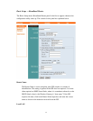
External Components
This section describes the back and front panels of the Wireless Gateway in details.
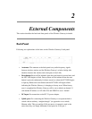
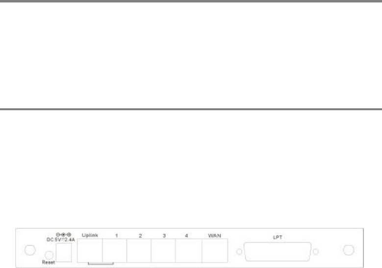
Back Panel
Following are explanations of the items on the Wireless Gateway's back panel:
• Antennae: The antennae at the back panel carry radio-frequency signals
between wireless stations and the Wireless Gateway's wireless bridge (the
interface between the wireless and wired parts of the LAN).
•
Reset button:
Reset will be initiated when the reset button is pressed once and
the LPT LED begins to flash. Factory Reset will be initiated when the reset
button is pressed continuously for three seconds or when the LPT LED begins
to light up. Release the reset button and the LPT LED will begin to flash
indicating the Wireless Gateway is changing to factory reset. When factory
reset is completed the Wireless Gateway will be set to default on channel 11
with default IP address as 192.168.0.254 and EES-ID is set as ‘default’.
• DC Input: For connection to the DC 5V power adapter.
•
Uplink port:
For connecting the Wireless Gateway to an upstream hub or
switch with an ordinary “straight-through” (as opposed to cross-wired)
Ethernet cable. This port and the LAN port next to it cannot be used at the
same time; they are simply differently wired ports for LAN port 1.