


8
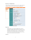
Note: All connections to the Wireless Gateway's LAN ports
should be made with Category 5 Ethernet cabling. Lower-grade
cabling cannot reliably carry 100-Mbps signals.
• LAN ports 1 through 4: Switched, auto-negotiating 10/100-Mbps Ethernet
ports for connecting end nodes (or downstream hub- or switched-based
clusters of end nodes) to the Wireless Gateway.
• WAN port: 10-Mbps Ethernet port for connection to a DSL or cable modem
or router.
• Parallel port: A Centronics-type connector for a standard printer cable.
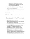
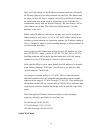
Front Panel
The Wireless Gateway's LED indicators are located on the unit's front panel:
• Power: Illuminates whenever the unit has power.
• Wireless: Illuminates when the wireless AP (access point) is ready but idle;
flashes when there is activity on the wireless link.
• LAN 1 to LAN 4 Link/Act: Each of these indicators illuminates when there is
a good but idle link on the corresponding LAN port, flashes when packets are
received/transmitted on the link.
• LAN 1 to LAN 4 100M: Each of these indicators illuminates when the
corresponding LAN port is operating at 100 megabits per second.
• WAN Link: Illuminates when there is a good link on the WAN port.
• WAN Act: Illuminates whenever unit has power, flashes when there is
activity on the WAN port.
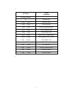
• LPT: Flashes three times then goes off to indicate a successful Power-On
Self-Test. Flashes on and off later during normal operation when there’s
printing activity. If the self-test detect any component error, then the LPT LED
will continuously signal the error according to the following table. In the
event of any such error signal, contact your dealer for correction of the faulty
unit.