


Installation
DRAFT
E Copyright Nokia Telecommunications Oy
NTC C33539002SE_A0
4-15
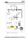
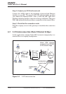
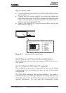
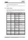
Step 1: Connect cables
D Connect the mains power cord to your M10 and the other end to the
power outlet.
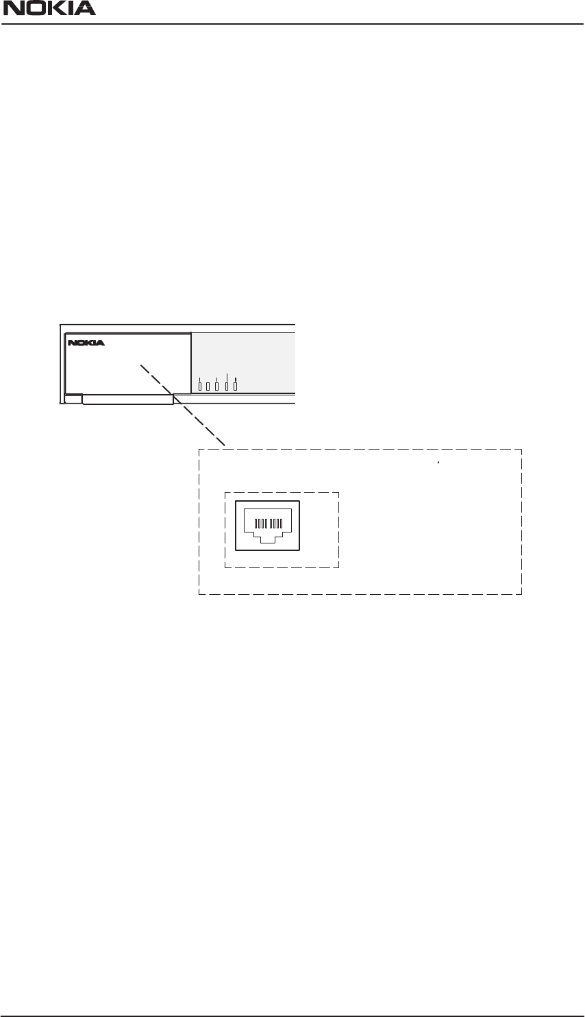
D Connect the M10 console cable to the console port behind the
hatch in the front panel of your M10. Connect the other end of the
cable to the serial port of your PC/terminal. A special cable is
needed, type designation E64320.01.
D Turn on your Nokia M10. The green status indicator and the red
DSL indicator light up.
OK EXIT
DNT2M
DSR DCD RTS CTS
18
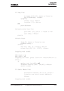
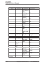
Node Manager Connector
(RJĆ45)
1. 107 (Const. ON)
2. 108 (IN)
3. 109 (OUT)
4. SG
5. 103 (IN)
6. 104 (OUT)
7. 105 (IN)
8. 106 (OUT)
Figure 4-5 Location of the console port
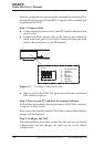
Step 2: Turn on your PC and start the terminal software
Set the following terminal software parameters: 9600, 8, no parity, no
flow control.
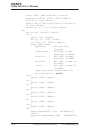
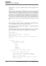
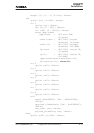
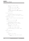
Step 3: Configure the M10 using CLI commands
The configurations given here assume that the unit uses its default
configurations and the changes are done on top of the default
configuration.
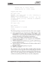
The Nokia M10 command line interface includes a step mode to
automate the process of entering configuration settings. When you use
the Config step mode, the CLI prompts you for all required and
optional information. You can enter the configuration values