


Page 24 of 46 Install ISDN BRI hardware
553-3901-200 Standard 7.00 January 2002
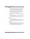
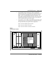
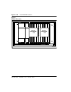
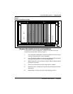
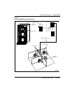
Connect Meridian 1 modules to the MDF
Meridian 1 modules connect to the MDF using NE-A25B cables with 50-pin
D-type male connectors on each end. One end of the cable plugs into the I/O
panel at the rear of the Meridian 1 module and the other end plugs into the
MDF.
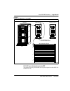
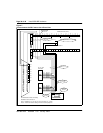
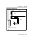
Figure 6 shows the cable connection between the Meridian 1 and the MDF.
1 Determine the number of NE-A25B cables needed to connect one
module to the MDF.
2 Label each end of the cable specifying the module number, the
connector name (A, B, C), and the card type (SILC or UILC).
3 Plug one end of a cable into the appropriate connector on the I/O panel
at the rear of the Meridian 1 module. Plug the other end of the cable
into the corresponding connector on the MDF.
4 Properly identify cables on the MDF. For example, plug the cable into
connector A on the I/O panel and into the connector labeled A on the
MDF if an SILC or UILC is installed in slot 0 of an IPE module.
5 Repeat steps 2 through 4 for all cables in that module.
6 Repeat steps 1 through 5 for all modules containing SILCs and/or
UILCs.
7 Lay all the cables neatly and fasten them with cable ties.
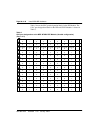
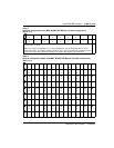
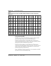
8 Label the MDF, as necessary, using Table 2 through Table 5.
—————————— End of Procedure ——————————