


Install ISDN BRI hardware Page 35 of 46
ISDN Basic Rate Interface Installation
Connect the ISDN BRI terminals to the DSL
ISDN BRI terminals are connected to DSLs using modular cables up to 10
meters (33 feet) long, with RJ-45 plugs on each end. One end of the cable
plugs into the terminal and the other end plugs into the wall outlet.
Note: All ISDN BRI terminals should comply with CCITT, ANSI,
ETSI NET-3, INS NET-64, National ISDN, 1TR6, Numeris VN2, and
D70 standards for terminals, and be compatible with Meridian 1. For a
list of compatible terminals, refer to the ISDN Basic Rate Interface:
Product Description (553-3901-100).
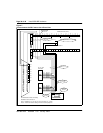
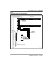
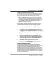
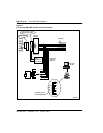
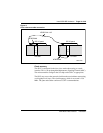
Figure 9 illustrates a terminal connection to the S/T interface; Figure 10
illustrates a network termination (NT1) connection to the U interface.
1 Plug one end of the modular cable into the ISDN BRI interface
connector on the terminal, and the other end of the modular cable into
the wall outlet.
2 For an SILC S/T interface terminal with an optional auxiliary power
source, plug the power source into the wall outlet, then plug the cable
into the power source's RJ-45 jack. This power source must supply
power only to the local ISDN BRI terminal, not back into the DSL
through the RJ-45 wall outlet. The power adapter is supplied with the
terminal.
3 Program the terminal parameters, such as the SPID and TEI, as
required by the type of terminal. For detailed information pertaining to
this procedure, refer to the section “Initialize ISDN BRI terminals”,
found in ISDN Basic Rate Interface: Administration (553-3901-300).
4 Repeat steps 1 and 3 for each terminal to be connected.
—————————— End of Procedure ——————————
Connect the terminating resistors
DSLs require that a terminating resistor
(Part Number A0378866) be
connected at the end of each loop. See ISDN Basic Rate Interface: Product
Description (553-3901-100), for engineering rules and locations of
terminating resistors. The end of the S/T interface loop has a RJ-45 jack to
plug in the telephone cable. Plug the terminating resistor into the RJ-45 and
then plug the telephone cable into the terminating resistor. Note that for every
port there is one loop with only one terminating resistor per loop. Each loop
may have up to eight telephones.