


Install ISDN BRI hardware Page 39 of 46
ISDN Basic Rate Interface Installation
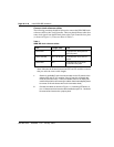
The loop number and location of the primary and secondary clock source is
configured in the Digital Data Block overlay 73. Refer to the ISDN Basic Rate
Interface: Administration (553-3901-300).
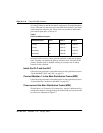
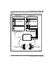
The following procedure should be followed to provide clock referencing on
the SILC.
Note: For procedures on how to install the QPC775/QPC471 Clock
Controller on the various Meridian 1 systems, please refer to ISDN PRI:
Installation (553-2901-201).
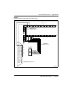
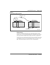
1 Maintain the same polarity on each transmit and receive. Rewire the
selected Tx and Rx pairs (applicable to DSL0 and DSL1), to exchange
the Tx and Rx pair position. This rewiring is done at the Main
Distribution Frame (MDF).
2 Remove the phantom power jumpers (two jumpers per DSL) from the
pin headers.
3 Place the SILC in the selected IPE slot.
4 Configure the selected DSL as TE mode (in overlay 27).
5 Enable the clock in overlay 60, to output the clock references to the
IPE back plane pins.
6 Configure the Clock Controller card to accept ISDN BRI clock
reference.
7 Check the appropriate messages from the Clock Controller to ensure
that it is synchronized to the proper clock reference (this is done using
overlay 60).
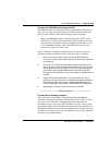
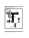
8 Connect the ISDN BRI clock reference cables to the Clock Controller,
using the procedures which follow.
—————————— End of Procedure ——————————