


Page 30 of 46 Install ISDN BRI hardware
553-3901-200 Standard 7.00 January 2002
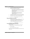
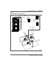
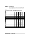
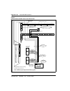
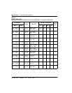
Figure 7
Cross-connect the SILC port to the office wiring
1
2
3
4
5
6
7
8
9
10
11
12
13
14
15
16
17
18
19
20
21
22
23
24
26
27
28
29
30
31
32
33
34
35
36
37
38
39
40
41
42
43
44
45
46
47
48
49
25 50
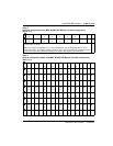
Port 0
Port 1
Port 2
Port 3
Port 4
Port 5
Port 6
Port 7
1
2
3
4
5
6
7
8
R+
T+
T-
R-
P-
P+
WHT/ORG
BLU/WHT
WHT/BLU
ORG/WHT
GRN/WHT
WHT/GRN
1
2
3
4
5
6
7
8
R+
T+
T-
R-
P-
P+
WHT/ORG
BLU/WHT
WHT/BLU
ORG/WHT
GRN/WHT
WHT/GRN
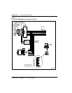
NE-A25B cable connector connecting
distribution frame connector A
Note 1: Substitute Tx- Tx+ Rx- Rx+ for every occurance of T- T+ R-R+
Note 2: Transmit and receive labeling is from the network perspective
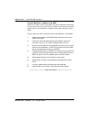
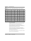
T- T+ R+ R- T- T+ R+ R- T- T+ R+ R- T- T+ R+ R- T- T+ R+ R-
Port 1
Port 0
Port 2 Port 3 Port 4
26 27 29 30 31 32 33 34 3528
12345678910
A
B
1234567891011121314151617181920
A
B
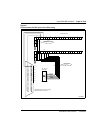
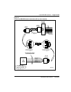
DSL 2 DSL 3
RJ - 45 type
wall outlet
RJ - 45 type
wall outlet
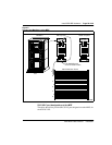
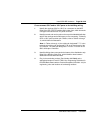
Port 0
Distribution frame (Note 1)
Power Source 2
Auxilary Power Source if more that 2 W
are required for DSL 1
Cross connect wires or
cable for DS1
Maximum stub length
1 m or 3.3 feet
DSL 1 wiring for
SILC Port 0
100 Ohm
Loop terminator
resistor box
A0378866