


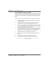

Install ISDN BRI hardware Page 27 of 46
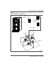
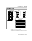
ISDN Basic Rate Interface Installation
T
T-T+R+R-
0
T-T+R+R-
1
T-T+R+R-
2
T-T+R+R-
3
T-T+R+R-
4
T-T+R+R-
5
T-T+R+R-
6
T-T+ R+R
7
T
U
T-T+R+R-
0
T-T+R+R-
1
T-T+R+R-
2
T-T+R+R-
3
T-T+R+R-
4
T-T+R+R-
5
T-T+R+R-
6
T-T+ R+R
7
U
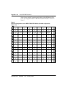
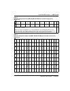
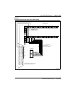
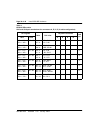
Note 1: For the SILC port designations shown in this table, substitute Tx- Tx+ Rx+ Rx- for every
occurrence of T- T+ R+ R-.
Note 2: The cable pair designated Tx- Tx+ is the transmit pair. The pair designated Rx+ Rx- is the
receive pair. An SILC port supplies 2 watts of power at -48 V (-40 V for international), simplexed over the
transmit and receive pairs, where the transmit pair is negative with respect to the receive pair.
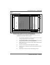
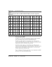
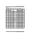
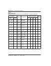
Table 3
UILC port designation labels at the MDF: NT8D37 IPE Module (16-cable configuration)
(Part 1 of 2)
A TR
0
TR
1
TR
2
TR
3
TR
4
TR
5
TR
6
TR
7
A
B TR
0
TR
1
TR
2
TR
3
TR
4
TR
5
TR
6
TR
7
B
C TR
0
TR
1
TR
2
TR
3
TR
4
TR
5
TR
6
TR
7
C
D TR
0
TR
1
TR
2
TR
3
TR
4
TR
5
TR
6
TR
7
D
E TR
0
TR
1
TR
2
TR
3
TR
4
TR
5
TR
6
TR
7
E
F TR
0
TR
1
TR
2
TR
3
TR
4
TR
5
TR
6
TR
7
F
G TR
0
TR
1
TR
2
TR
3
TR
4
TR
5
TR
6
TR
7
G
H TR
0
TR
1
TR
2
TR
3
TR
4
TR
5
TR
6
TR
7
H
K TR
0
TR
1
TR
2
TR
3
TR
4
TR
5
TR
6
TR
7
K
Table 2
SILC port designations at the MDF: NT8D37 IPE Module (16-cable configuration)
(Part 2 of 2)
14
15
0
1
2
3
4
5
6
7
8