


Page 40 of 46 Install ISDN BRI hardware
553-3901-200 Standard 7.00 January 2002
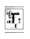
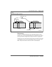
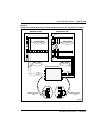
Connect clock reference cables
The following procedure should be followed to connect the ISDN BRI clock
reference cables to the Clock Controller. There are three different cables that
route clock signals from the IPE back plane to the Clock Controller face plate
(as shown in Figure 11). These are shown in Table 7.:
Note: Measure the distance between the IPE and CE modules to ensure
that you order the correct cable lengths.
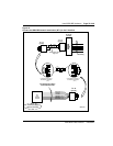
1 Search for available D-sub 9 connector slots on the I/O panels of the
selected IPE and CE I/O modules (if the I/O panel is equipped with
D-sub 9 connector slots). If none is available, look for an empty slot
used for 25 pair wire connectors (the cables contain two adapter plates
to convert an 25 wire slot to two D-sub 9 connector slots).
2 Connect the cables as shown in Figure 11; if choosing IPE slots 0, 4,
8, or 12 the transmit and receive cable installed on pins 72 - 79 should
be removed and secured to a proper place.
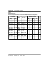
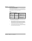
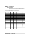
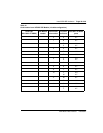
Table 7
ISDN BRI clock reference tables
Code Length (feet) Use
NTND70AA 1.5 Connects IPE back plane to
IPE I/O panel.
NTND71AA-AD 6.5, 12, 25, 42 Connects IPE I/O to CE I/O
panel.
NTND72AA 6.5 Connects CE I/O to Clock
Controller face plate.