


Install ISDN BRI hardware Page 29 of 46
ISDN Basic Rate Interface Installation
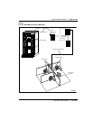
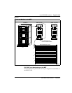
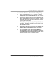
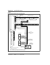
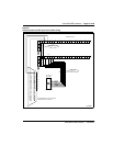
Cross-connect SILC and/or UILC ports to the building wiring
1 Identify the card type (SILC or UILC) for a connector on the MDF.
Refer to the IPE or CE/PE module card location form, which shows the
card type connected to each I/O panel connector.
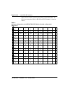
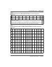
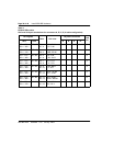
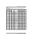
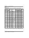
2 Identify transmit and receive pairs on the top of the labeled distribution
strip for the card type and module type you are connecting. To identify
SILC or UILC ports and their pin numbers, refer to Tables 4 through
10, which follow the illustrations.
Note: In Tables 4 through 10, the cable pair designated T- T+ is the
transmit pair and the pair designated R+ R- is the receive pair of the
S/T interface. The cable pair designated T R is the Tx and Rx of the
2B1Q full duplex U interface.
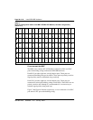
3 Identify building wires connected to the bottom of the distribution strip.
Refer to the Building Cable Plan, which identifies wires between
distribution frames and wall outlets.
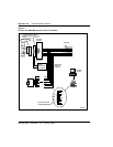
4 Plug in the terminating resistor (Part Number A0378866) at the
appropriate location in each S/T DSL. See “Engineering Guidelines” in
the ISDN Basic Rate Interface: Product Description (553-3901-100) for
engineering rules and locations of terminating resistors.