


Page 42 of 46 Install ISDN BRI hardware
553-3901-200 Standard 7.00 January 2002
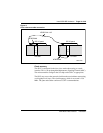
All of the S/T chips on the SILC could be configured as Terminal Equipment
Slaves (TES), but only the clocks recovered from DSL0 and DSL1 are routed
to the back plane connector pins. These clocks are provided as differential
pairs on back plane pins, as follows: in
Automatic clock recovery is done upon the expiration of the free run guard
timer. Tracking is restored to the primary reference clock, if defined. If the
primary reference clock is disabled, tracking is restored to the secondary
reference clock, if defined.
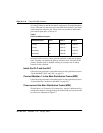
Install the SILC and the UILC
Follow the same procedures as described earlier for line applications (refer to
“Install the BRSC, SILC and UILC” on page 21).
Connect Meridian 1 to the Main Distribution Frame (MDF)
Follow the same procedures as described earlier for line applications (refer to
“Connect Meridian 1 modules to the MDF” on page 24).
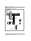
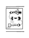
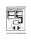
Cross-connect the Main Distribution Frame (MDF)
The Meridian 1, in Tie trunk or CO connectivity, requires a different wiring
configuration than for a line application; the transmit and receive pairs should
be reversed, as illustrated in Figure 12.
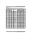
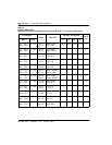
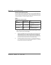
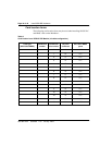
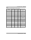
Table 8
Clocks as differential pairs
Differential pairs Pin # Row A Row B
Primary 73 +Ref 0A - Ref 0A
Primary 74 +Ref 1A - Ref 1A
Secondary 75 +Ref 0B - Ref 0B
Secondary 76 +Ref 1B - Ref 1A