


October 2006 703t server description
703t Server Hardware Installation 19
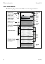
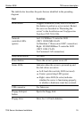
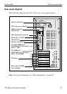
The table below describes the parts that are identified in the preceding
diagram:
Part Function
Reset button Triggers a hardware (cold) reset. Do not use
this button to perform a server restart. Restart
the server as described in “Restarting the
server” in the Installation and Configuration
Task List (555-7101-210).
Network
controller LEDs
(green)
Left: 10/100Base-T controller LED
(NIC1 10/100 MB: ELAN
for Meridian 1
*
/Succession 1000
*
connection)
Right: 10/100/1000Base-T controller LED
(NIC2 1 GB: CLAN
for Customer LAN connection)
Sleep mode button Not used
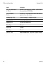
Power button Turns the server’s power on or off.
Status LEDs Indicates when the server is powered up and
the disk drives are active.
Left: hard drive activity LED (not used)
Center: power/sleep LED (green)
Right: status LED (bi-color) indicates
whether the server is functioning properly,
or whether a hardware event has occurred.
USB connector For future use
Floppy disk eject
button
Ejects the floppy disk.
Floppy drive Drive for 3-1/2 inch diskettes.