


Installing the server and connecting the peripheral devices Standard 1.04
50 CallPilot
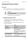
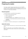
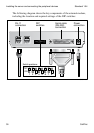
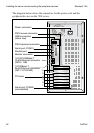
The following diagram shows the key components of the external modem,
including the location and required settings of the DIP switches:
G101445
RJ-11
connection
DIP
switches
Switch positions:
Serial cable
(RS-232)
connection
Power
connection
12345678
12345678
OFF
ON