


94 Appendix A Technical specifications
NN46110-311 02.01
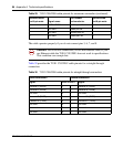
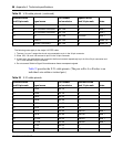
The cable operates properly if you do not connect pins 3, 6, 7, and 8.
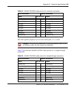
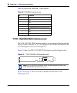
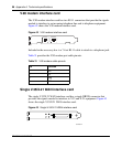
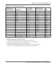
Table 30 provides the T1/E1 CSU/DSU cable pinouts for a straight-through
connection.
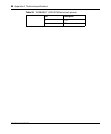
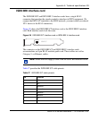
5 TXDA->RXDA wht/blu pair 1A 1
6 not used green pair 3B 6
7 not used wht/brn pair 4A 7
8 not used brown pair 4B 8
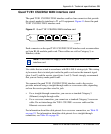
Caution: For crossover connections, do not use Ethernet cable. If you
use Ethernet cable the T1/E1 CSU/DSU does not work to specifications.
This condition can corrupt data.
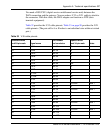
Table 30 T1/E1 CSU/DSU cable pinouts for straight-through connection
Nortel termination Remote termination
Signal Pin # to Pin # Signal
Receive A (RXDA) 1 1 Receive A (RXDA)
Receive B (RXDB) 2 2 Receive B (RXDB)
not used 3 3 not used
Transmit B (TXDB) 4 4 Transmit B (TXDB)
Transmit A (TXDA) 5 5 Transmit A (TXDA)
not used 6 6 not used
not used 7 7 not used
not used 8 8 not used
Table 29 T1/E1 CSU/DSU cable pinouts for crossover connection (continued)
Standard-wired
end 8-pin male Signal name
Pair number
and conductor
Special-wired
end 8-pin male