


98 Appendix A Technical specifications
NN46110-311 02.01
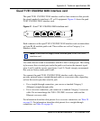
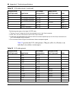
The following notes apply to the single V.35 DTE cable:
1. The term “no conn” means the wire is not connected to a pin in the 34-pin connector.
2. Wires 12B, 13A, and 14B connect to pin B in the 34-pin connector.
3. At each end, the cable shield and connector shell must connect respectively to pin A of the 34-pin connector and
pin 1 of the standard 28-pin connector.
4. Do not connect Shield to Signal Ground because these are separate signals.
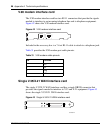
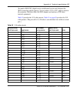
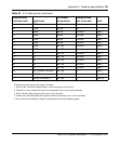
Table 33 provides the X.21 cable pinouts. (The pair suffix A or B refers to an
individual wire within a twisted pair.)
25 TM pair 12A NN
26 M0<-SIGNAL GROUND pair 12B B Note 2
27 M1<-SIGNAL GROUND pair 13A B Note 2
28 M2 pair 13B no conn Note 1
1 SHIELD pair 14A A Notes 3,4
7 SIGNAL GROUND pair 14B B Notes 2,4
Table 33 X.21 cable pinouts
Standard-wired
end 28-pin male Signal name
Pair number
and conductor
Standard-wired
end 15-pin male Notes
2 TXDA pair 1A 2
14 TXDB pair 1B 9
3 RXDA pair 2A 4
16 RXDB pair 2B 11
15 TXCA pair 3A 6
12 TXCB pair 3B 13
17 RXCA pair 4A pair 5A Note 1
9 RXCB pair 4B pair 5B Note 1
24 SCTEA pair 5A pair 4A Note 1
11 SCTEB pair 5B pair 4B Note 1
4 RTSA pair 6A 3
19 RTSB pair 6B 10
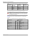
Table 32 V.35 cable pinouts (continued)
Standard-wired
end 28-pin male Signal name
Pair number
and conductor
Special-wired
end 34-pin male Notes