


96 Appendix A Technical specifications
NN46110-311 02.01
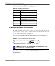
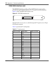
V.90 modem interface card
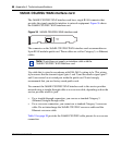
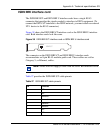
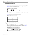
The V.90 modem interface card has two RJ-11 connectors that provide the signals
needed to interface to an incoming telephone line and to telephone equipment.
Figure 42 shows the V.90 modem interface card.
Figure 42 V.90 modem interface card
Included in the accessory box is a 7-foot RJ-11 cable to attach to a telephone jack.
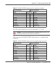
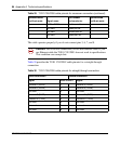
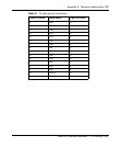
Table 31 provides the V.90 modem port cable pinouts.
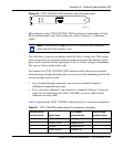
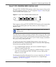
Single V.35/X.21 WAN interface card
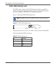
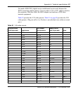
The single V.35/X.21 WAN interface card has a single DB28S connector that
provides the signals needed to interface to V.35 and X.21 equipment. Figure 43
shows the single V.35/X.21 WAN interface card.
Figure 43 Single V.35/X.21 WAN interface card
Table 31 V.90 modem cable pinouts
Pin Function
1N/C
2Tip
3 Ring
4N/C
PHONE
LINE
CS160011A