


20 Chapter 1 Overview
N0087114 1.0
Administration and maintenance tools
R2MFC card configuration involves the following:
• Internal link configuration for the PRI internal link to the Norstar system. The internal link
uses preset characteristics and, therefore, does not require localization.
• External link configuration of the MFC-R2 E1 the external interface to public network. The
external link allows for localization in different countries.
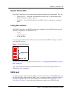
External link configuration is performed using the DIP switches on the front of the R2MFC card or
by using the CLI, which is accessed through a serial port on the faceplate of the R2MFC card.
Internal link configuration is performed using a Norstar digital telephone set. Refer to
“Configuring the R2MFC card” on page 35 for information on how to use the configuration
tools.
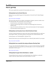
R2MFC card faceplate elements
The faceplate of the R2MFC card consists of the following elements:
• “System Status LEDs” on page 21
• “Config DIP switches” on page 21
• “RS232 port” on page 21
• “E1 Status LEDs” on page 22
• “Bantam jacks” on page 22
• “BNC and RJ-48 connectors” on page 22
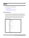
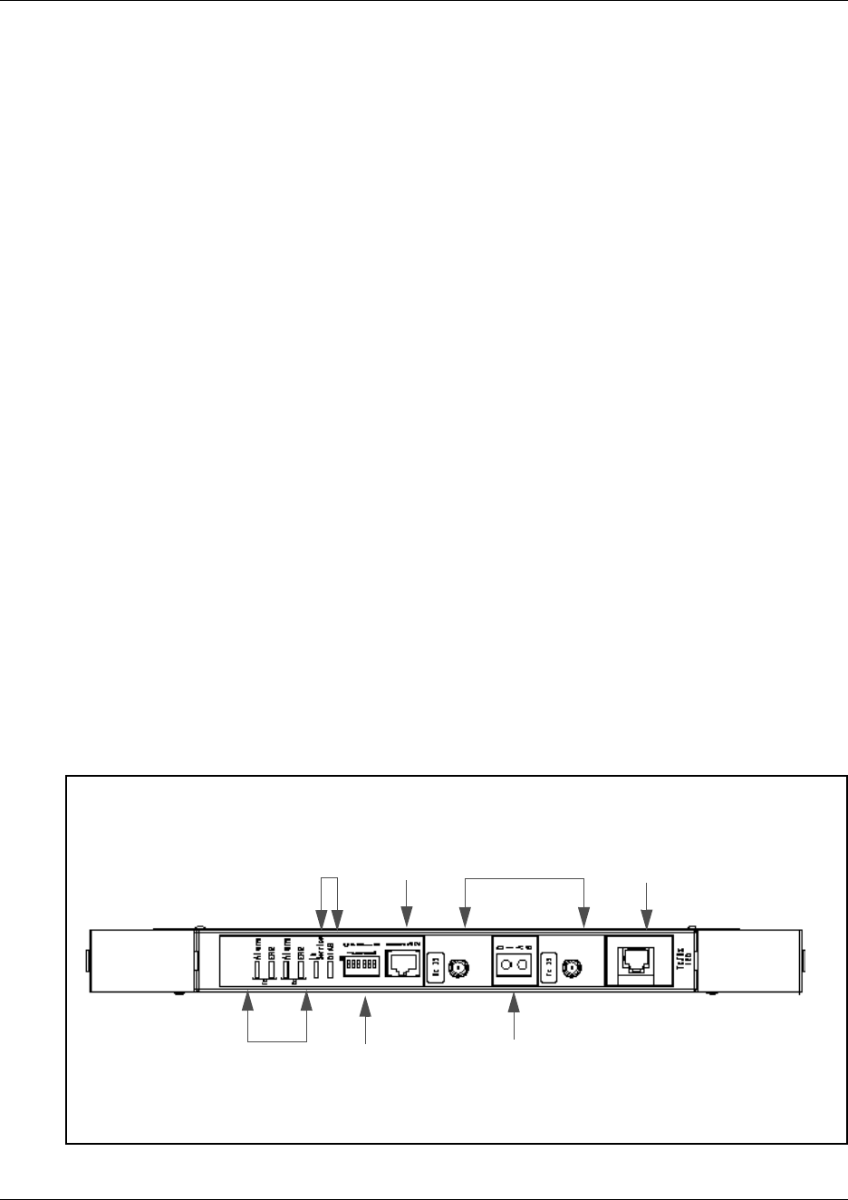
Figure 2 illustrates the placement of these elements.
Figure 2 R2MFC card faceplate
120
Ω
E1
RJ-48
75
Ω
E1 BNC
Bantam
jacks
E1 status
4 LEDS
RJ-45
DIP
switches
Card status
2 LEDS
Card laying horizontally