


36 Chapter 4 Configuring the R2MFC card
N0087114 1.0
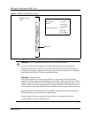
R2MFC side (External Link) configurable parameters
Physical line characteristics
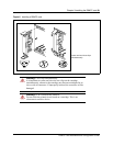
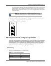
The R2MFC card has two options for physical connections on the faceplate:
1 RJ-48 connector for twisted pair cable (line impedance of 120 Ohms)
2 a pair of mini BNC connectors for coax cables (line impedance of 75 Ohms)
The BNC connectors can have one of the following:
• TX shielding connected to ground (default)
• RX and TX shielding not connected to ground
Only one of the two connector types can be active. The default active interface is the BNC
connector. The BCN connector is part of the country-specific defaults for Mexico variant 1. Each
of the country codes activates the appropriate connector, based on the country standard for
connectors.
The active interface can be customized in the firmware through the CLI by using commands in the
COnfig directory.
E1 framing
The external link uses Channel Associated Signaling on timeslot 16, therefore; TS16 multiframe
format is always used. In addition, optional CRC4 multiframe can be used (for monitoring digital
transmission quality), instead of basic “alternate frame” format.
The CRC4 multiframe option is activated by the firmware as part of the country-specific defaults.
PCM coding is A-law.
These settings can be customized in the firmware through the CLI by using commands in the
ALarm directory.
Line signaling
Line signaling (for example, seize, answer, and disconnect) are implemented by R2 Channel
Associated Signaling known as ABCD bits. Only the two bits AB are used for line signaling. The
state (value) of the bits indicate the signal.
Note: Configure changes made to the framing parameters in both the R2MFC card and the
Norstar System.