


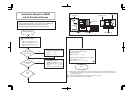
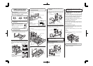
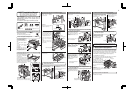
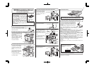
1. Turn off the main switch of the main unit of the printer.
2. Remove the cables connected to the control PWB unit.
(Example) MFP control PWB
(Example) MFP control PWB
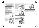
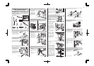
7. Turn on the main switch of the main unit of the printer.
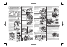
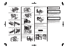
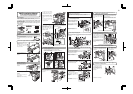
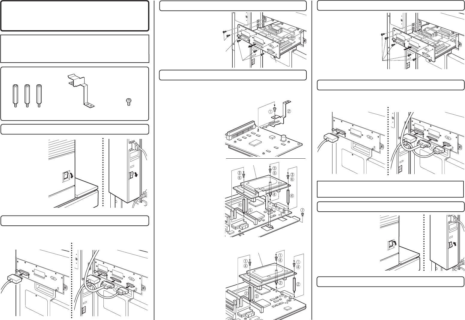
4. Mount the HDD expansion PWB to the control PWB.
8. Check the operation.
5. Attach the control PWB.
Turn the main switch
located on the front
side of the main unit to
the "OFF" position.
Then remove the
power plug from the
outlet.
Insert the power plug of the
main unit of the printer to the
outlet.
Then, turn the main switch
located on the front side of the
main unit to the "ON" position.
• For setting change of the printer drivers on the computer, see the supplied
operation manual.
Then, execute printing from the computer using the print hold function to check
for proper printing.
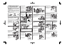
Remove all the cables connected to the control PWB unit of the main unit of the
printer.
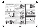
3. Remove the control PWB unit.
Remove the five screws that
fix the control PWB unit to
the main unit of the printer.
Then, hold the two grips and
pull out the printer control
PWB unit to remove it from
the main unit.
Attach the control PWB unit to
the main unit of the printer and
fix it using five screws.
6. Connect the cables to the control PWB.
Connect all the cables that have been removed in step 2 to the original positions
of the printer control PWB unit.
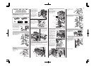
<1> Remove the screw at the position shown in the
illustration among the screws that secure the hard
disk to the HDD expansion PWB.
<2> Attach the supplied grounding plate to the HDD
PWB as shown in the illustration
and secure it using the screw that
has been removed in step <1>.
<3> Remove the three screws
shown in the illustration among
the screws that fix the printer
control PWB.
<4> Mount supplied three PWB
fixing screws to the positions from
which three screws have been
removed.
<5> Insert the HDD expansion
PWB to the connector of the
printer control PWB.
<6> Fix the HDD expansion PWB
to the PWB fixing screws using
the three screws that have been
removed in step 1.
<7> Secure the grounding plate that
has been attached to the HDD
expansion
PWB to the controller mounting
plate using the supplied screw.
<1> Remove the three screws
shown in the illustration among
the screws that fix the MFP
control PWB.
<2> Mount supplied three PWB
fixing screws to the positions from
which three screws have been
removed.
<3> Insert the HDD expansion
PWB to the connector of the MFP
control PWB.
<4> Fix the HDD expansion PWB
to the PWB fixing screws using
the three screws that have been
removed in step 1.
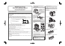
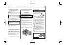
Parts included
PWB fixing screws: 3 pcs.
"OFF"
"ON"
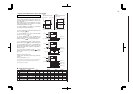
<Before installation>
• Start installation after checking that the DATA and
COMMUNICATION indicators on the operation panel are
neither lit nor blinking.
• In case of printer control PWB ..................................................................................
• In case of MFP control PWB ......................................................................................
• The procedure (shape of PWB) varies with the printer control PWB and
the MFP control PWB.
Screws
• In case of printer control PWB
• In case of printer control PWB
• In case of MFP control PWB
• In case of MFP control PWB
Grip
Grip
Screws
Screws
B83HD Installation Manual
HDD expansion PWB
Grounding plate
: 1 pcs.
screws: 1 pcs.
HDD expansion PWB
* If another peripheral device must be installed, carry out
the following step at the end of the installation work.
"OFF"
"ON"
FOR USE WITH COMPATIBLE OKI DIGITAL PRINTERS.
SEE OKI DIGITAL PRINTER SERVICE MANUAL OR
INSTALLATION MANUAL TO DETERMINE SUITABILITY.
13