67
4.8.3 Device Setting and Configuration
The Meter and End Devices should first be configured and ready to use.
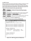
Make sure to have the following settings in the ”Network” web page of the Meter
(Figure 4.21) .
Number of Connections = 5
Port = 2000 (other values may be acceptable as long as Mail Notifier is setup
with the same Port number)
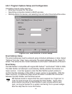
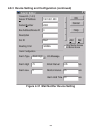
Then on the Mail Notifier Alarm Editor, set the BusAddress/DeviceID to match
the Device ID number for an End Device and set the Reading Cmd to a
Command String from the following table:
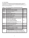
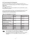
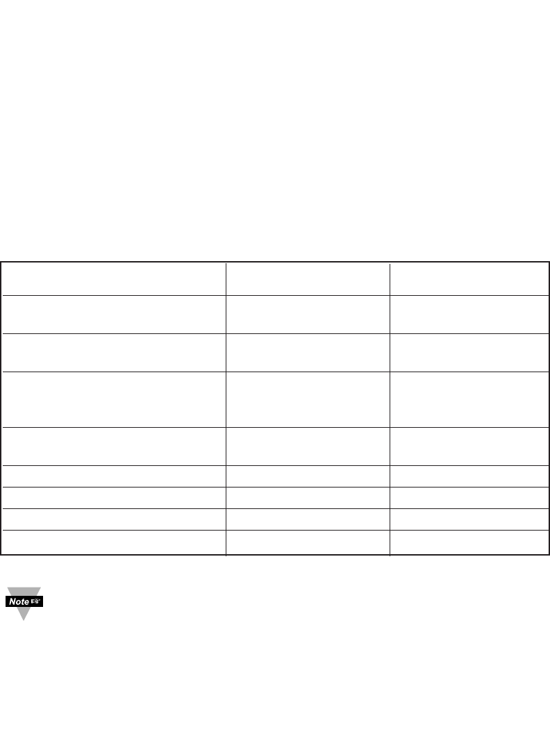
Table 4.2 Mail Notifier Commands
Desired Value to Monitor Reading Command Actual Command
String String (see Note 2)
Temperature1 (Thermocouple) SR##a *SR05a\r
in scale configured at Meter
Temperature1 (Thermocouple) SR##o *SR05o\r
in Degree C
Temperature2 (Ambient at SR##b *SR05b\r
End Device sensor) in scale
configured at Meter
Temperature2 (Ambient at SR##p *SR05p\r
End Device sensor) in Degree C
Battery voltage (mV) SR##j *SR05j\r
Signal Level SR##h *SR05h\r
Success Rate SR##i *SR05i\r
Sleep Interval SR##1 *SR051\r
1. The commands used in Mail Notifier are symbolic commands rather
than actual Meter commands described in Table 4.1.
2. The sample commands in the table above are shown for a sensor
with Device ID of 5 such that SR##a, for example, is sent as
*SR05a\r.


