


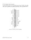
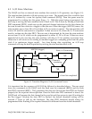
4.4 Scan List Register
One entry to the scan list register contains a 16-bit word or two 8-bit bytes. It specifies the
internal channel and gain selection in the high byte or MSB, and the external channel and gain
selection in the low byte or LSB, in addition to other control and configuration settings. The
external selections are used for expansion card channels (up to 128), while the internal
selections are for channels on board the DAQP card. Expansion cards are not included as part
of the DAQP series data acquisition system, however, they can be purchased separately from
your vendor.
The number of entries in the scan list ranges from 1 to 2048. There are no dependencies
implied among the entries of the scan list. The user may choose any valid gain combination
for any channel, internal or external. Channels can be scanned in any order required, repeated
or not, with the same or different gain for each entry.
The scan list must be flushed before programming to guarantee the integrity of each entry.
There must be an even number of bytes programmed into the scan list, with the low byte
sitting at an even offset followed by the high byte, otherwise the channel scan result will be
unpredictable.
It is strongly recommended that the differential/single-ended control bit (bit 14, MSB) be
programmed the same for all the entries in the scan list. Single-ended configuration should be
selected if there are expansion cards connected to the DAQP card. The synchronous sample
hold bit (bit 6, LSB) is reserved for expansion cards.
The first channel flag (bit 7, LSB) has to be set for the first (and ONLY the first) entry of the
scan list. The DAQP card hardware relies on this bit to tell the end (or the start) of the scan. In
normal operations, the DAQP card starts one scan when triggered, (software or TTL trigger in
one-shot mode or sampling pulse triggers from the pacer clock in continuous mode). During
the scan, each entry in the scan list will be processed until it finds the entry that has the first
channel flag set to ‘1’. The hardware then stops scanning and waits for the next trigger. The
scan will continue indefinitely if none of the list entries has the flag set to ‘1’. On the other
hand, if more than one entry has the flag set to ‘1’, the scan list will then be chopped into
pieces. Each piece will require a trigger to be scanned. Should the flag be set to ‘1’ on an entry
other than the first, a “starting offset” will be introduced to the scan list. Channel scanning will
start from the entry with the flag set to ‘1’, run through the list, turn around and end at the one
before it. Although this may be useful for diagnosis or special applications, it is the abnormal
way of setting the first channel flag and should be avoided unless absolutely necessary.
DAQP-208/208H/308 Users Manual 30