


5
.
2
.
5
Pacer Clock (base + 4, + 5, + 6)
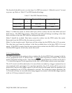
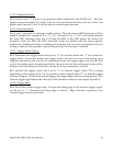
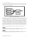
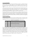
The pacer clock is actually a 24-bit auto re-load frequency divider. It contains a 24 bit divisor
register, a 24 bit counter, an internal clock pre-scaler and a clock source multiplexer. Figure
5-1 shows the pacer clock block diagram.
24 bit Register
24 bit Counter
Pacer Clock
Output
10 MHz
External Clock Input
Divide by 2
Divide by 10
Divide by 100
Figure 5-1. Pacer Clock Block Diagram
The clock source selection is specified by bits 6 and 7 in the control register (base + 2). The
24-bit register occupies 3 ports, in which the low byte is located at base + 4, the middle byte at
base + 5 and the high byte at base + 6. All three registers are write only. The pacer clock will
not generate a clock pulse output until the A/D circuit is running (after receiving the arm
command in pre-trigger mode or after receiving a trigger when pre-trigger is not selected).
The pacer clock is not functioning in one-shot mode. In continuous mode, the trigger will
serve as the first clock output pulse, and load the counter from the register. The counter will
count down the input clock pulse until it is zero and then an output clock pulse is generated
and the counter is reloaded. Pacer clock output will continue until the DAQP card receives the
stop command which is generated by writing a ‘1’ to bit 4 of the auxiliary control register (base
+ 7).
The clock rate is determined as follows: Rate = Source Frequency / (Divisor Count + 1) .
Example 1
If an internal clock source is applied at 100 kHz (control register bits 7,6 = 11) and the divisor
count is 49, then the pacer clock output frequency = 100 kHz / (49 + 1) = 2 kHz.
Example 2
If an external clock source is applied at 120 kHz (control register bits 7,6 = 00) and the divisor
count is 39, then the pacer clock output frequency = 120 kHz / (39 + 1) = 3 kHz.
DAQP-208/208H/308 Users Manual 50