


5
.
2
.
9
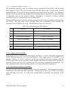
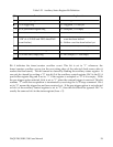
Auxiliary Control Register (base + 15)
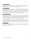
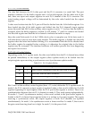
This register configures the operation of A/D, D/A and the timer counter. It is 8-bit wide and
write only. Bit 7 picks between TTL and analog trigger source. Bit 6 sets the pre-trigger
option. Bit 5 is for the timer/counter interrupt control. Bits 3 and 4 determine the
timer/counter operation modes while bit 2 selects the timer/counter clock source. Bits 1 and 0
specify the D/A update modes.
Table 5-21. Auxiliary Control Register Bit Definition
00 = Direct update
01 = When timer/counter overflows
10 = When ext. gate goes low to high
11 = When pacer clock fires
D/A update mode
1,0
1 = External, 0 = Internal (1 MHz)Timer/Counter clock source2
00 = Reload
01 = Pause
10 = Go
11 = Go/Pause by external gate signal
Timer/Counter mode4,3
1 = Enabled, 0 = Disabled
by writing ‘0’ into this bit
Timer/Counter interrupt
Clear overflow event latch
5
1 = with pre-trigger, 0 = withoutPre-trigger option6
0 selects TTL trigger
1 selects analog trigger
External trigger source7
Explanation
Function
Bit
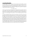
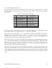
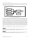
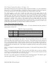
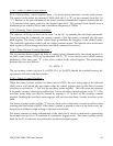
5.2.10 Auxiliary Status Register (base + 15)
Bits 0-3 and bit 7 in this register are structured so that these bits can be referenced without the
associated side effect of “clear after read” on latched events. The “clear after read” side effect
is preserved for the status register (base + 2). Bits 0 and 1 are the data FIFO flags. Bit 2 is the
data lost event latch. These three bits are defined exactly the same as in the status register.
Bit 3 in this register is the logic “OR” of the two event latches in the status register, (EOS event
latch and data FIFO event latch). This bit is “1” if either the EOS or FIFO event is latched. It is
“0” if both the EOS and FIFO events are cleared by power up, reset or reading the status
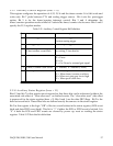
register. Table 5-22 lists the bit definition.
DAQP-208/208H/308 Users Manual 57