


bit 3 of the command register at base + 7). The integrity of the latched count is guaranteed by
the logic design.
The timer port is allocated at base + 10 (low byte) and base + 11 (high byte). The 16 bit reload
register is accessed when writing to the port, while the read-latch register is accessed when
reading the port. The up-counter cannot be accessed directly.
Bit 4 of the auxiliary control register selects the timer clock source. The 1 MHz internal clock
source will be selected if the bit is set to “0”. The external clock source (or the counter pulse
input) is selected if the bit is set to “1”. Because of the I/O pin confinement, the timer external
clock input is shared with the pacer clock external input (also shared as digital input bit 2).
Bits 3 and 2 in the auxiliary control register (base + 15) control the timer operation. There are
four modes (modes 0, 1, 2 and 3 corresponding to 00, 01, 10 and 11 respectively). In mode 0,
the counter will stop and reload the initial value when it detects the rising edge of the selected
clock source. In mode 1, the counter will pause counting, but not reload as it does in mode 0.
Mode 2 is the counting mode in which the counter will count up each time it detects the rising
edge of the selected clock source. In mode 3, the counter will be controlled by the external
gate signal. Counting proceeds when the gate signal is high and pauses when it is low.
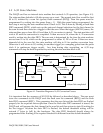
Three I/O pins are associated with the timer: the external clock source input (shared with the
pacer clock), external gate control (shared with the D/A) and the timer overflow pulse output
(TTL) which goes high when the timer reaches its final count (hexadecimal FFFF).
The reload register can be set up for both counting and timing operations. The value written
into the reload register, referred to as X for the sake of discussion, determines the divisor or
modulus for timing and counting. Since the final count before reloading is always 65535
(hexadecimal FFFF) for the up-counter, the reload (initial) value determines where the
counting will start. Therefore, 65536 - X will be the divisor for timing operations or the
modulus for counting operations. For example, a divide-by-2 timer (or modulus 2 counter)
can be configured by setting X equal to 65534, while X = 0 implies the divisor is 65536 (or the
modulus is 65536). It is recommended that X = 65535 (hexadecimal FFFF) be avoided because
the timer will stick at this final count even though the hardware will not reject or indicate
such a setting. Changing the reload register “on the fly” is allowed, but the setting will not
take effect until the up-counter reaches its final count (65535 or hexadecimal FFFF). The next
clock rising edge will load the counter with the new setting.
Bit 5 in the auxiliary control register (base + 15) enables (when set to 1) or disables (when set
to 0) the timer interrupt. When enabled, an interrupt will be sent each time the up-counter
overflows (passes through its final count). Whether the timer interrupt is enabled or not,
setting bit 4 in the auxiliary status register to “1” indicates the overflow event has been
detected at least once since the last time the bit was cleared by writing a “1” into bit 5 of the
auxiliary control register. Reading the auxiliary status register will not clear this bit.
DAQP-208/208H/308 Users Manual 36