


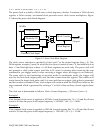

5.2.8 Timer/Counter Port (base + 10, base + 11)
The timer/counter port can be accessed as either a 16 bit word at base + 8, or two consecutive
bytes at base + 8 (low byte) and base + 9 (high byte). The port contains a 16 bit reload register,
a 16 bit up-counter and a 16 bit read latch register and the associated control logic.
The reload register is write only. It holds the initial value (or the reload value) for the
up-counter. Each time the counter overflows, the next clock rising edge will reload the counter
with this value. The same value is also loaded to the counter as it’s initial value in mode 0.
The read latch register is read only. It holds the current count of the up-counter when a latch
command is received. The content of this register will not change until the next latch
command is received. The up-counter cannot be accessed directly. It will reload on the next
rising edge of the selected clock from the reload register either when it reaches its final count
of 65535 (hexadecimal FFFF) or when the timer/counter is in mode 0.
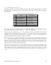
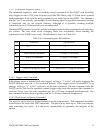
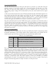
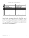
5.2.8.1 Timer/Counter Operation Modes
Bits 3 and 4 in the auxiliary control register (base + 15, write) determine the timer modes as
summarized in Table 5-20.
Table 5-20. Timer/Counter Modes
Operation controlled by the gate input:
Gate = Low: Pause, Gate = High: Start/Continue
3
11
Start/Continue210
Pause101
Stop and reload the up-counter from the reload register
0
00
Timer/Counter OperationModeBits 4,
3
Mode 0 is used for reloading the up-counter. Note that reloading will only occur when the
next rising edge of the selected clock source is received. The internal clock source requires at
least 1 ms to complete reload. When the timer/counter is used for counting external pulses, it
is recommended that mode 0 and the internal clock source be selected first to guarantee the
initial reload by the internal clock Once reload is completed, then the source can be switched
to external.
Mode 1 is designed to temporarily pause the up-counter. In this mode the up-counter will be
frozen.
Mode 2 is considered the “go” mode. The up-counter will either start to count or continue
counting up on the rising edge of the selected clock source. If the up-counter reaches it’s final
count, then it will reload on the next clock rising edge.
In mode 3, up-counter operation is controlled by the external gate signal. The counter “goes”
when the signal is high (“1”) and stops when the signal is low (“0”).
DAQP-208/208H/308 Users Manual 55