


5
.
2
.
1
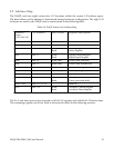
Data FIFO Register (base + 0)
The data FIFO register is considered as the access port to the data FIFO, which holds up to
2048 data words from the A/D conversion results. The port is also used for programming the
data FIFO thresholds, as explained later in this section.
Note: Although the data FIFO register is 8 bits wide, it is strongly recommended that the
register be accessed as a 16 bit word to guarantee integrity. The low byte (LSB or the least
significant byte) should always be accessed first, followed by the high byte (MSB or the most
significant byte). Two consecutive bytes should be read from or written into the port each
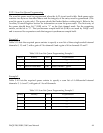
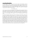
time it is accessed. The following table illustrates bit allocation.
Table 5-5. Data FIFO Register Bit Allocation
D8D9D10D11D12D13D14D15MSB
D0D1D2D3D4D5D6D7LSB
Bit 0
Bit 1
Bit 2
Bit 3
Bit 4
Bit 5
Bit 6
Bit 7
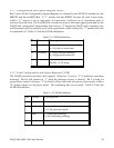
5.2.1.1 Data FIFO Operation Modes
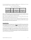
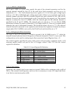
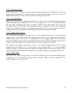
Depending on the mode of operation, the 16-bit word read from or written into the register has
different meanings as shown in the following table.
Table 5-6. Data FIFO Operation Mode
Read data FIFO
Not allowed
Read
Write
Run1, data FIFO3
Verify data FIFO threshold
Not allowed
Read
Write
Run
0, threshold
2
Read data FIFO
Write data FIFO (diagnosis)
Read
Write
Idle
1, data FIFO
1
Verify data FIFO threshold
Program data FIFO threshold
Read
Write
Idle0, threshold0
Operation
Acces
s
A/D
Selection Bit
Mod
e
The “selection bit” is also called the “program/access” control bit, as defined in the auxiliary
control register (base + 7). Mode 0 is the FIFO program mode, under which the two
consecutive words (four bytes) written into the register address will set the almost full and
DAQP-208/208H/308 Users Manual 40