


After the thresholds are programmed, set the access control bit to “1” by writing a byte of 01H
into the auxiliary control register. This will make the following read/write operation access
the data bytes in the FIFO instead of it’s thresholds. It is recommended that the access control
bit be set to “1” when sending other commands (flush scan list, stop A/D, or trig/arm) to the
DAQP card by writing into the auxiliary control register. A useful tip for safe operation is to
set the bit to “0” only when flushing and programming the FIFO thresholds. Although the
almost empty threshold is never used, it must be programmed because the four configuration
bytes must be accessed as an entire entity.
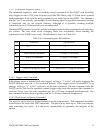
5.2.6.6 Latch Timer/Counter Command
This command will latch the current value of the timer/counter into the 16 bit read latch
register and can be executed if the timer/counter is running (on the fly) or not. The latched
value will not change until a new latch command is issued again.
5.2.7 D/A Data Port (base + 8, base + 9)
The D/A data port can be accessed either as a 16-bit word at base + 8, or two consecutive
bytes at base + 8 (low byte) and base + 9 (high byte). The port is write only. For simplicity,
the 16-bit word is assumed in the following discussion.
Bit 12 to 15 selects the D/A channel, in which bit 13, 14 and 15 must all be set to “0”, while bit
12 is “0” for selecting D/A channel 0 or “1” for D/A channel 1.
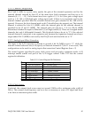
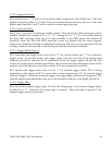
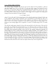
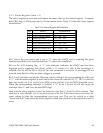
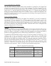
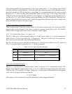
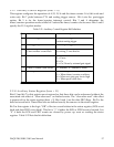
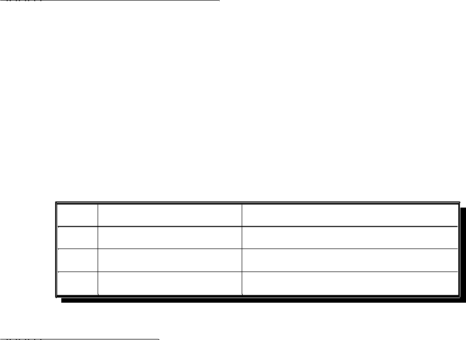
Table 5-18. D/A Data Port Bit Definition
-2048..2047 in 2’s complement
D/A output code value
11-0
“0” for channel 0, “1” for channel 1
D/A channel selection
12
all “0”Reserved15-13
Explanation
Definition
Bits
5.2.7.1 D/A Channel Output
Bits 0 to 11 specify the D/A channel data, which is always in 2’s complement format. The
bipolar D/A channel output ranges from -5v to +5v, with the corresponding code value from
-2048 to 2047. The actual D/A output voltage (U in Volts) can be determined from the output
code value C using the following formula:
U = (C*5/2048)
The output of D/A channel 1 is used for setting the analog trigger threshold.
DAQP-208/208H/308 Users Manual 53