


5
.
2
.
7
.
2
D/A Port Interface
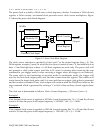
The data link between the D/A data port and the D/A converter is a serial link. The port
interface contains a 16 bit buffer register and a 16 bit shift register. On the other side of the
link, there are input and output registers in each D/A channel of the D/A converter. The
actual analog output voltage will be determined by the code value loaded into the output
register.
A data word written into the D/A port will first be latched into the 16 bit buffer register. It is
then loaded into the 16 bit shift register and shifted into the D/A channel’s input register
across the serial link. Bit 5 in the auxiliary status register is set to “1” to show that the buffer is
occupied when the buffer register is written. It will remain “1” until it’s contents are loaded
into the shift register and then the bit is cleared to indicate the buffer is empty.
Since the serial link needs 16 of the 2 MHz clock cycles to complete one 16 bit data word, it
will take about 8 ms for each data word transfer. The buffer register is loaded into the shift
register when the latter has finished shifting. It is recommended that this bit be checked and
the buffer register be emptied before writing to it otherwise the original data in the buffer
register may be corrupted. The interface hardware will neither prevent this from happening
nor report it as an error.
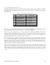
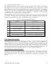
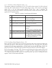
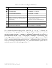
5.2.7.3 D/A Update Modes
Depending on the D/A update mode, the data word shifted into the D/A channel may either
be passed immediately to the output register (direct update mode) or be loaded into the
output register upon receiving a synchronous event (synchronous update mode).
Table 5-19. D/A Update Modes
Each time the A/D pacer clock fires
3
11
Each time when the gate control goes from low to high210
Each time when the timer overflows
1
01
Direct update, immediately after the data word is written
0
00
UpdateModeBit 1, 0
Bits 1 and 0 of the auxiliary control register (base + 15, write) define the D/A update mode. In
mode 0, the D/A converter output register is updated when a data word is shifted to it’s shift
register, bypassing it’s input register, after the D/A port buffer register is written. There is no
synchronization between the two D/A channels in mode 0. They each operate independently.
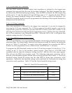
In modes 1, 2 and 3 (synchronous modes), a data word written to the port buffer register is
loaded to the D/A channel input register before it is written to it’s output register. Then upon
receiving a synchronous event, the output registers of both D/A channels are updated
simultaneously. In mode 1, the synchronous event is timer overflow. In mode 2, the event is
the gate control moving from low to high. In mode 3, it is the pacer clock.
DAQP-208/208H/308 Users Manual 54