151
Setting Tag Data Links Section 6-2
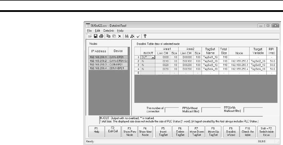
Node List The following items will be displayed in the Node Area on the left side of the
window.
• IP Address: The IP address of the node.
• Device: The name (model number) of the device at the node.
Note The node list will display the node registered in the Network Configurator.
Nodes cannot be added or deleted from this window.
Data Link Table
Information
The data link table of the node selected on the left will be displayed on the
right. Each row specifies word that are allocated for data links for that node.
Each row specifies the node settings for the words (area) where a data link
has been created. You can set only area 1 or both area 1 and area 2.
• IN/OUT: Specifies whether the link inputs data to the node or outputs data
from the node. OUT can be selected only once. Once OUT has been
selected for one row, IN will automatically be selected for other rows. A
asterisk will be displayed if the Over Load function is disabled. (See note.)
Note The Over Load function is used to clear output data when all out-
puts are turned OFF from the CPU Unit of the PLC. This setting is
not necessary for inputs.
(a) Over Load function enabled: Output data will be cleared to all ze-
ros when all outputs from the PLC are turned OFF from the CPU
Unit.
(b) Over Load function disabled: Output data will be maintained even
when all outputs from the PLC are turned OFF from the CPU Unit.
• Area 1, Link CH: The I/O memory address of the first word in link area 1
• Area 1, Size: The number of words in link area 1. (See note.)
• Area 2, Link CH: The I/O memory address of the first word in link area 2
• Area 2, Size: The number of words in link area 2. (See note.)
Note With the Network Configurator, the PLC status will be shown at the
beginning of each area. The PLC status includes the CPU Unit op-
erating status (operating information and error information).


