26
Nomenclature and Functions Section 2-2
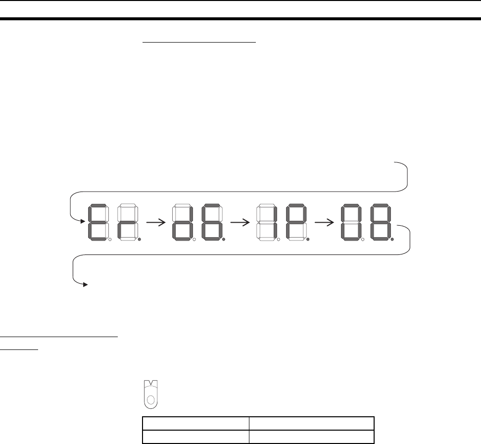
Right and Left Dot LEDs
If an error occurred in two or more devices with the same rightmost byte in
their IP addresses, the Right Dot LED will be lit while the devices’ error is
being displayed.
Example: Displaying the Following Errors
• A d6 error (failed to establish connection) occurred with IP address
10.0.1.8.
• A d6 error (failed to establish connection) occurred with IP address
10.0.2.8.
2-2-2 Switch Settings
Unit Number Setting
Switch
The Unit Number Setting Switch sets the unit number of the EtherNet/IP Unit
or built-in EtherNet/IP port as a CPU Bus Unit. The unit number determines
which data area words are allocated to the Unit to contain data such as con-
trol bits, flags, status information, and connection information.
Note The unit number is factory-set to 0.
The unit number can be set to any number in the setting range (0 to F), as
long as the same number is not set on another CPU Bus Unit in the same
PLC.
Note (1) Use a small screwdriver to make the setting, and be sure not to damage
the rotary switch.
(2) Always turn OFF the PLC’s power supply before setting the unit number.
(3) The unit number is factory-set to 0.
(4) If the same unit number is set on more than one CPU Bus Unit mounted
in a PLC, a unit number duplication error will occur in the PLC and the
EtherNet/IP Unit or built-in EtherNet/IP port will not be able to start oper-
ating.
Setting method Setting range
One-digit hexadecimal 0 to F
F
E
D
C
B
A
9
8
7
6
5
4
3
2
1
0


