231
Communicating between OMRON PLCs Section 8-6
Note 1. With CS/CJ-series PLCs, the Communications Port Enabled Flags at bits
0 to 7 in word A202 turn OFF even when the PCMR(260) instruction is be-
ing executed using the ports corresponding to those flags.
2. Before using the sample program as is, confirm that the memory areas
(words and bits) used in the sample program are not already being used in
the user program o r by Special I/O Units.
When the Communications Port Enabled Flag for port 7
is ON, and SEND(090) is not being executed, the trans-
mission execution program will start when execution
condition CIO 000001 turns ON.
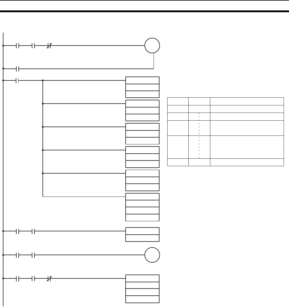
Input CIO 120002 remains ON from the start of
RECV(098) execution until completion.
Control Data Creation
Word
Number of reception words = 16
Source network number = 3
Source node number = 32
Source unit address = 0
Response required.
Communications port No. used = 7
Number of retries = 5
Response monitor time = Default
A total of 16 words of data beginning from word A100
at network number 3, node number 32, unit address 0
(the PLC) is received at word CIO 2000 onwards of the
local node.
Reset Input Creation
Reception Error Display
Reception Data Processing
If there is no reception processing completion error, the
16 words of data received from word CIO 2000 on-
wards is stored at D00040 onwards.
KEEP
120002
000001
A20207
(See note 1.) 120000
120003
@MOV(21)
@MOV(21)
@MOV(21)
@MOV(21)
@MOV(21)
@RECV(98)
DIFU(13)
120002 A20207
121001
120002 A21907
Execution
condition
(Continued from previous page.)
120002
@XFER(70)
120002
120003
A21907
(See note 1.)
S
R
Contents Meaning
00 10
00 03
20 00
07 05
00 00
D0005
D0006
D0007
D0008
D0009
D00040
120003
D00005
2000
A100
D00009
#0000
D00008
#0705
D00007
#2000
D00006
#0003
D00005
#0010
2000
#0016


