


2-67
2 Instructions
CP1E CPU Unit Instructions Reference Manual(W483)
Timer and Counter Instructions
2
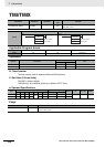
TIM/TIMX
Function
Hint
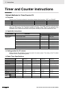
• A TIM/TIMX(550) instruction’s PV and Completion Flag can be refreshed in the following ways
depending on the timer number that is used.
Precautions
• Timer numbers are shared with other timer instructions. If two timers share the same timer number,
but are not used simultaneously, a duplication error will be generated when the program is checked,
but the timers will operate normally. Timers which share the same timer number will not operate prop-
erly if they are used simultaneously.
• Timers will not operate properly when the CPU Unit cycle time exceeds 4s. Use timer instructions
when the cycle time is no longer than 4s.
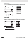
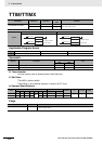
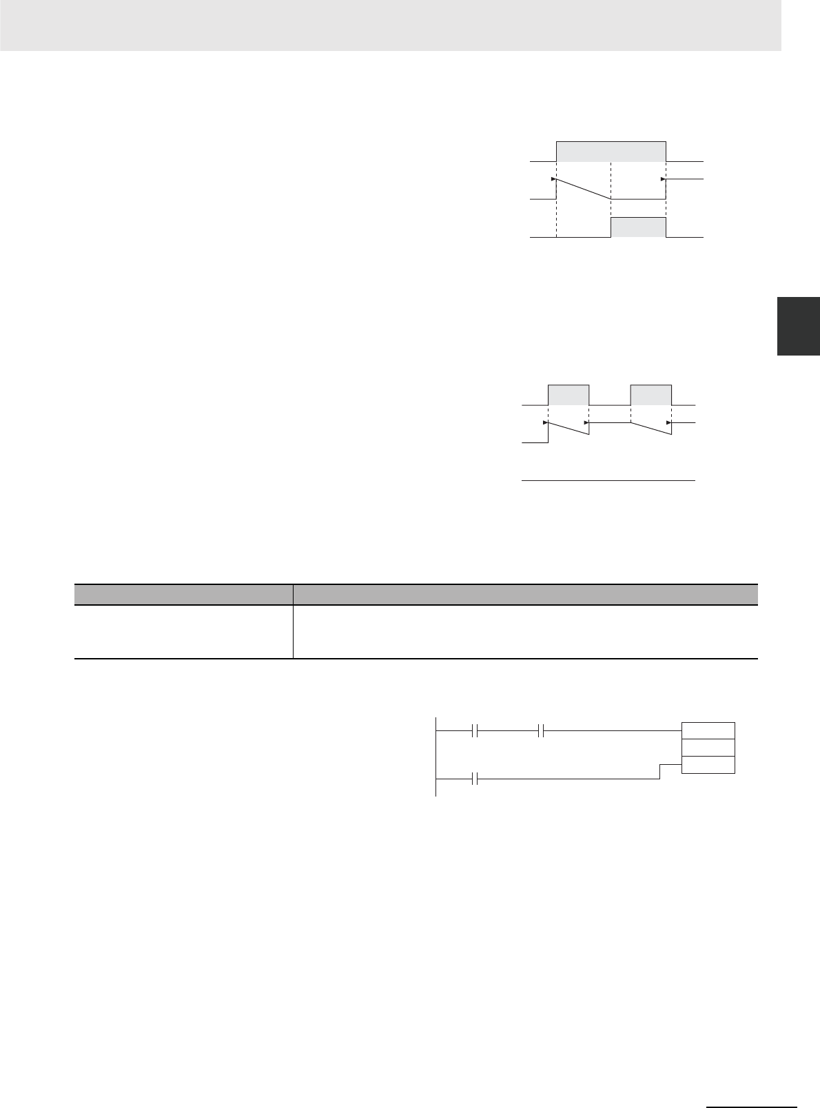
• Timers will be reset or paused in the following cases. (When a timer is reset, its PV is reset to the SV
and its Completion Flag is turned OFF.)
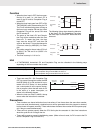
• When the timer input is OFF, the timer spec-
ified by N is reset, i.e., the timer’s PV is
reset to the SV and its Completion Flag is
turned OFF.
• When the timer input goes from OFF to ON,
TIM/TIMX(550) starts decrementing the PV.
The PV will continue timing down as long as
the timer input remains ON and the timer’s
Completion Flag will be turned ON when
the PV reaches 0.
• The status of the timer’s PV and Comple-
tion Flag will be maintained after the timer
times out. To restart the timer, the timer
input must be turned OFF and then ON
again or the timer’s PV must be changed to
a non-zero value (by MOV(021), for exam-
ple).
• The setting range for the set value (SV) is 0
to 999.9 s for TIM and 0 to 6,553.5 s for
TIMX(550).
• The timer accuracy is -0.01 to 0 s.
Refresh timing Description
Execution of TIM/TIMX(550) • The PV is updated every time that TIM/TIMX(550) is executed.
• The Completion Flag is turned ON if the PV is 0.
The Completion Flag is turned OFF if the PV is not 0.
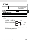
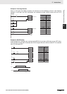
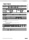
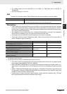
• Timers are reset (PV = SV, Completion Flag
OFF) by power interruptions unless the IOM
Hold Bit (A500.12) is ON and the bit is pro-
tected in the PLC Setup. It is also possible
use a clock pulse bit and a counter instruc-
tion to program a timer that will retain its PV
in the event of a power interruption, as
shown in the following diagram.
• When the timer set value is #0000, timeup
occurs when the instruction is executed.
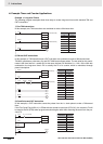
ON
OFF
0
ON
OFF
SV
Timer input
Timer PV
Completion
Flag
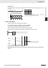
ON
OFF
0
ON
OFF
SV
Timer input
Timer PV
Completion
Flag
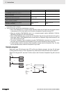
The following timing chart shows the behavior
of the timer’s PV and Completion Flag when
the timer input is turned OFF before the timer
times out.
CNT
N
S
Count input
Reset input
Execution
condition
1-s clock
pulse bit