


2-343
2 Instructions
CP1E CPU Unit Instructions Reference Manual(W483)
Step Instructions
2
SNXT/STEP
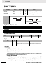
Proceeding to the Next Step
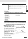
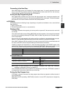
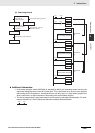
When SNXT(009) occurs in the middle of the step program area, it is used to proceed to the next
step. It turns OFF the previous control bit and turns ON the next control bit B, for the next step,
thereby starting step B (all instructions after STEP(008) B).
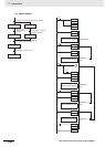
Ending the Step Programming Area
When SNXT(009) is placed at the very end of the step program area, it ends step execution and
turns OFF the previous control bit. The control bit specified for B is a dummy bit. This bit will however
be turned ON, so be sure to select a bit that will not cause problems.
STEP(008)
STEP(008) functions in following 2 ways, depending on its position and whether or not a control bit has
been specified.
1. Starts a specific step.
2. Ends the step program area (i.e., step execution).
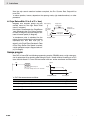
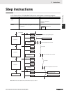
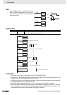
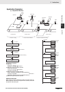
Starting a Step
STEP(008) is placed at the beginning of each step with an operand, B, that serves as the control bit
for the step.
The control bit B will be turned ON by SNXT(009) and the instruction in the step will be executed
from the one immediately following STEP(008). A200.12 (Step Flag) will also turn ON when execu-
tion of a step begins.
After the first cycle, step execution will continue until the conditions for changing the step are estab-
lished, i.e., until the SNXT(009) instruction turns ON the control bit in the next STEP(008).
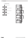
When SNXT (009) turns ON the control bit for a step, the control bit B of the current instruction will
be reset (turned OFF) and the step controlled by bit B will become interlocked.
Handling of outputs and instructions in a step will change according to the ON/OFF status of the
control bit B. (The status of the control bit is controlled by SNXT(009)). When control bit B is turned
OFF, the instructions in the step are reset and are interlocked. Refer to the following tables.
Interlock Status (IL)
Note Indicates all other instructions, such as TTIM(087), TTIMX(555), SET, REST, CNT, CNTX(546),
CNTR(012), CNTRX(548), SFT(010), and KEEP(011).
The STEP(008) instruction must be placed at the beginning of each step. STEP(008) is placed at
the beginning of a step area to define the start of the step.
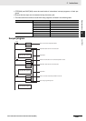
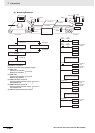
Ending the Step Program Area
STEP(008) is placed at the end of the step program area without an operand to define the end of
step programming.
When the control bit preceding a SNXT(009) instruction is turned OFF, step execute is stopped by
SNXT(009).
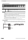
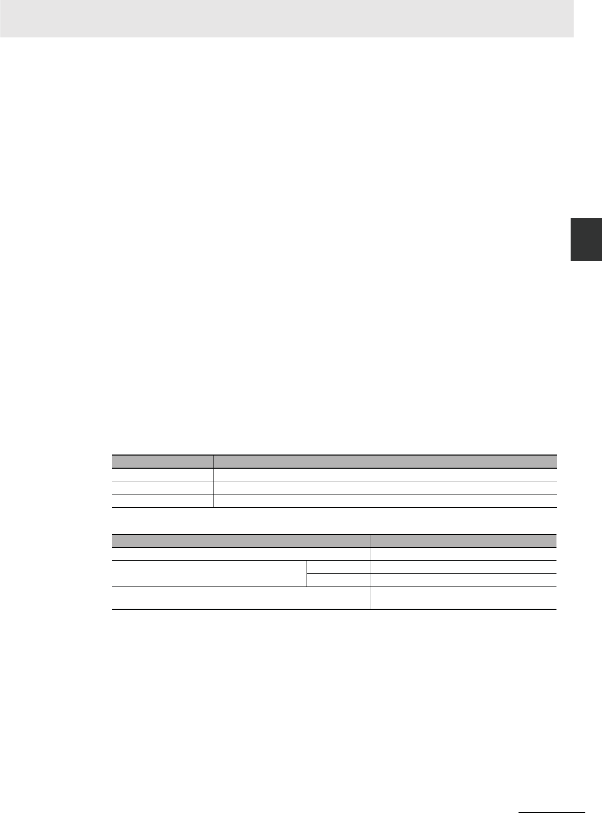
Control bit status Handling
ON Instructions in the step are executed normally.
ON→OFF Bits and instructions in the step are interlocked as shown in the next table.
OFF All instructions in the step are processed as NOPs.
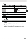
Instruction output Status
Bits specified for OUT, OUT NOT All OFF
TIM, TIMX(551), TIMH(015), TIMHX(551), TMHH(540),
TIMHHX(552), TIML(542), and TIMLX(553)
PV 0000 hex (reset)
Completion Flag OFF (reset)
Bits or words specified for other instructions (see note) Holds the previous status (but the instructions are not
executed)