


2-359
2 Instructions
CP1E CPU Unit Instructions Reference Manual(W483)
Basic I/O Unit Instructions
2
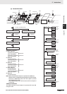
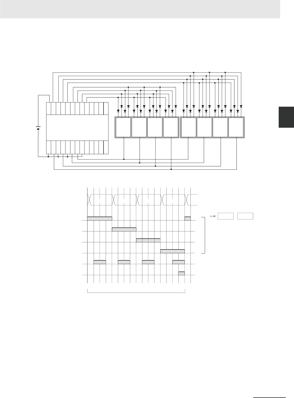
DSW
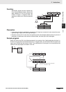
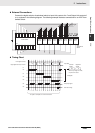
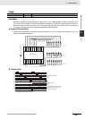
External Connections
Connect the digital switch or thumbwheel switch to Input Unit contacts 0 to 7 and Output Unit contacts 0
to 4, as shown in the following diagram. The following example illustrates connections for an A7B Thum-
bwheel Switch.
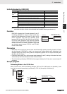
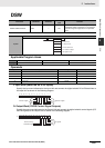
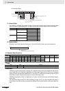
Timing Chart
COM
00
01
02
03
04
05
06
07
08
09
10
11
IN
CP1W-20EDT
OUT
COM
00
COM
01
COM
02
03
COM
04
05
06
07
8
No. 1No. 2No. 3No. 4No. 5No. 6No. 7No. 8
4 2 1
A7B
Thumbwheel
Switch
Switch
Switch Switch Switch Switch Switch Switch Switch
00
01
02
03
04
05
O
10
0
10
1
10
2
10
3
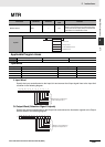
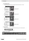
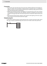
D+1 D
0 1 2 3 4 5 6 7 8 9 10 11 12 13 14 15 16
I
Leftmost
4 digits
Rightmost
4 digits
Input data
CS signals
One Round Flag
RD (read) signal
16 cycles to complete one round of execution
Eight digits: 00 to 03, 04 to 07
Four digits: 00 to 03
When only 4 digits are read,
only word D is used.