


2-361
2 Instructions
CP1E CPU Unit Instructions Reference Manual(W483)
Basic I/O Unit Instructions
2
MTR
MTR
Applicable Program Areas
Operands
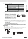
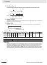
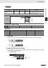
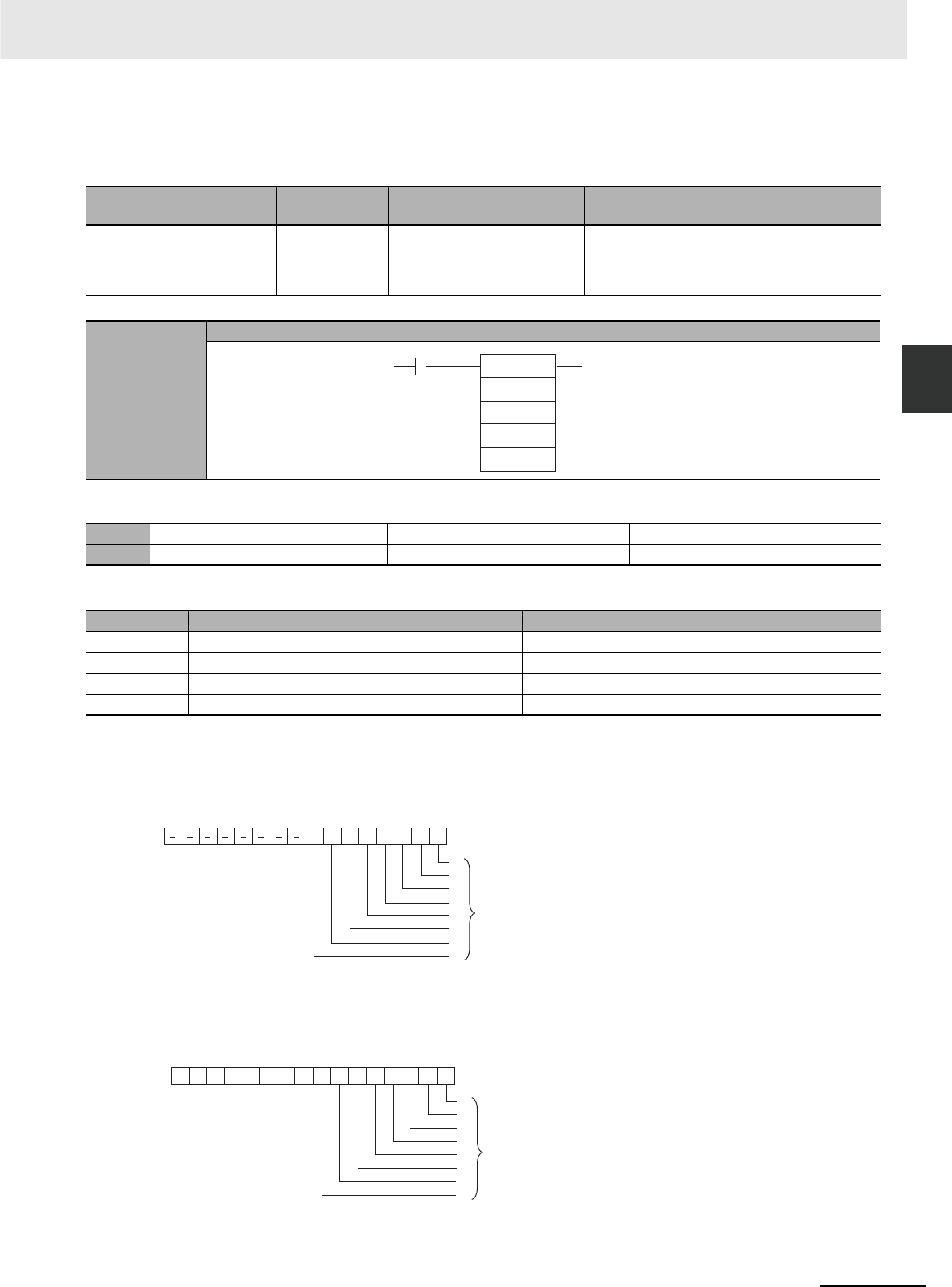
I: Input Word
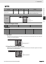
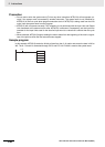
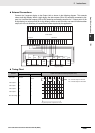
Specify the input word allocated to the Input Unit and connect the 8 input signal lines to the Input Unit
as shown in the following diagram.
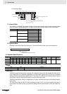
O: Output Word (Selection Signal Outputs)
Specify the output word allocated to the Output Unit and connect the 8 selection signals to the Output
Unit as shown in the following diagram.
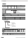
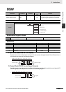
Instruction Mnemonic Variations
Function
code
Function
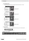
MATRIX INPUT MTR --- 213
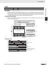
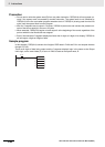
Inputs up to 64 signals from an 8 × 8 matrix con-
nected to an Input Unit and an Output Unit (using
8 input points and 8 output points) and stores that
64-bit data in the 4 destination words.
Symbol
MTR
Area Step program areas Subroutines Interrupt tasks
Usage OK OK Not allowed
Operand Description Data type Size
I Input word UINT 1
O Output word UINT 1
D First destination word ULINT 4
C System word WORD 1
I: Input word
O: Output word
D: First destination word
C: System word
MTR(213)
I
O
D
C
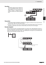
0123456789101112131415
I
0
1
2
3
4
5
6
7
Bits 00 to 07 correspond to
Input Unit inputs 0 to 7.
0123456789101112131415
O
0
1
2
3
4
5
6
7
Bits 00 to 07 correspond to
Output Unit outputs 0 to 7.