2 Instructions
2-14
CP1E CPU Unit Instructions Reference Manual(W483)
Precautions
When a logic block is connected by AND LOAD or OR LOAD instructions, the total number of AND
LOAD/OR LOAD instructions must match the total number of LOAD/LOAD NOT instructions minus 1. If
they do not match, a programming error will occur.
AND LD
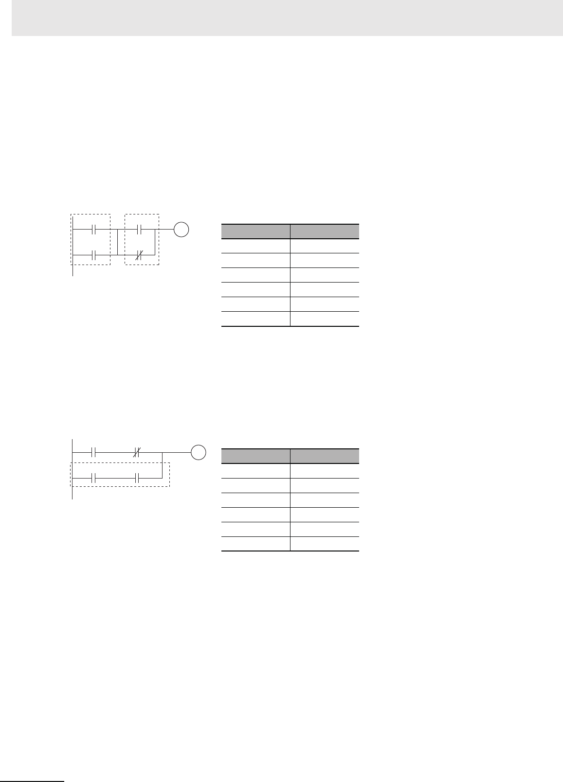
In the following diagram, the two logic blocks are indicated by dotted lines. Studying this example shows
that an ON execution condition will be produced when either of the execution conditions in the left logic
block is ON (i.e., when either CIO 0.00 or CIO 0.01 is ON) and either of the execution conditions in the
right logic block is ON (i.e., when either CIO 0.02 is ON or CIO 0.03 is OFF).
i
OR LD
The following diagram requires an OR LOAD instruction between the top logic block and the bottom
logic block. An ON execution condition would be produced either when CIO 0.00 is ON and CIO 0.01 is
OFF or when CIO 0.02 and CIO 0.03 are both ON. The operation of and mnemonic code for the OR
LOAD instruction is exactly the same as those for a AND LOAD instruction except that the current exe-
cution condition is ORed with the last unused execution condition.
i
0.00 0.02
0.030.01
100.00
Coding
Second LD: Used for first bit of next block connected in series to previous block.
Instruction Operand
LD 0.00
OR 0.01
LD 0.02
OR NOT 0.03
AND LD ---
OUT 100.00
0.00 0.01
0.030.02
100.01
Coding
Second LD: Used for first bit of next block connected in series to previous block.
Instruction Operand
LD 0.00
AND NOT 0.01
LD 0.02
AND 0.03
OR LD ---
OUT 100.01


