


20
2. System
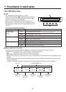
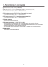
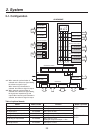
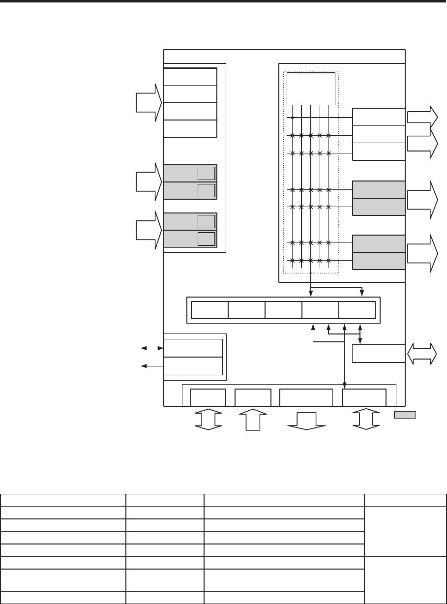
2-1. Configuration
AV-HS400AE
PGM
PVW
AUX
Multi
KeyOut
INPUT1(SDI)
INPUT2(SDI)
INPUT3(SDI)
INPUT4(SDI)
INPUT5 UC
UC
UC
UC
INPUT6
INPUT7
INPUT8
Black ColorBGD ColorBar FMEM1 FMEM2
REF
PGM1, 2(SDI)
OUTPUT1(SDI)
OUTPUT2(SDI)
OUTPUT4
OUTPUT3
OUTPUT6
OUTPUT5
PGM1, 2
OUTPUT
1, 2
OUTPUT
5, 6
OUTPUT
3, 4
VIDEO INPUT VIDEO OUTPUT
INTERNAL VIDEO
CONTROL
Output Matrix
INPUT
1–4
INPUT
7, 8
INPUT
5, 6
REF IN/OUT(1)
SD
Memory Card
RS422 GPI TALLY OUT LAN
: Option
REF OUT(2)
INPUT SLOT1(Option)
OUTPUT SLOT1(Option)
OUTPUT SLOT2(Option)
INPUT SLOT2(Option)
1: When external synchronization is
selected as the reference signal setting,
the reference signal is input.
When internal synchronization is
selected, the reference signal is output.
2: When external synchronization is
selected as the reference signal setting,
the signals are looped through and
output. When internal synchronization is
selected, the reference signal is output.
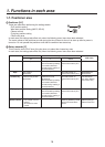
Table of optional boards
Board Model number Function Where connected
SDI Input Board AV-HS04M1
SDI input 2
lines
INPUT SLOT1 or
SLO
T2
Analogue Input Board A
V-HS04M2
Analogue component input 2
lines
DVI Input Board AV-HS04M3
DVI-I input 2
lines
Analogue Composite Input Board AV-HS04M6
Analogue composite input 2
lines
Analogue Output Board AV-HS04M4
Analogue component output 2
lines
OUTPUT SLOT1 or
SLOT2
DVI/Analogue Output Board A
V-HS04M5
DVI-I output 1 line
Analogue component output 1 line
SDI Output Board AV-HS04M7
SDI output 2
lines