


94
5. System settings
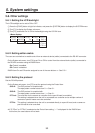
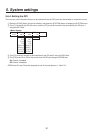
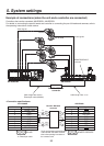
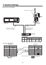
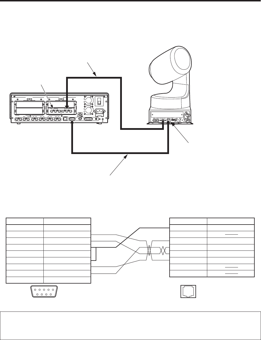
Example of connections (when the unit and a pan-tilt head are connected)
Pan-tilt heads that can be connected: AW-HE100N/E, AW-PH400E, AW-PH405E, AW-PH360L
Connections for AW-HE100N/E, AW-PH405E or AW-PH360L
POWER
1
REF
GPI
SLOT2
2
SLOT
4
2
34 SLOT1
1
SLOT2 8
~IN
SDI INPUTS
TALLY
6
6
INPUTS
SIGNAL
SDI OUTPUTS
GND
INOUT
3
INOUT
2
INOUT
1
INOUT
OUTPUTS
1
5 7
SLOT
OFF
2
SLOT1 5
SLOTSLOT
PGM
RS-422LAN
ON
ANALOG INPUTS
Y Pb
Pr
Y Pb
Pr
DVI INPUTS
ANALOG OUTPUTS
Y Pb
Pr
Y Pb
Pr
DVI/ANALOG OUTPUTS
Y Pb
Pr
DVI-I
DVI-I DVI-I
Analogue component signals
(For the connection specifications, refer to the
Operating Instructions of the AW-HE100N/E.)
Analogue Input Board
CONTROLLER connector
Cab
le length: Max. 200 m
Twisted pair cable (AWG24)
AV-HS400AE
AW-HE100N/E
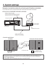
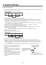
<Connection specifications>
1 FRAME GND
2 TXD –
3 RXD +
4 GND
5
6 GND
7 TXD +
8 RXD –
9 FRAME GND
NC
1
2
3
4
5
6
7
8
RXD –
GND
TXD –
RXD +
TXD +
RS-422
CONTROLLER
(CONTROL IN IP/RP)
12345
9 8 7 6
1.......8
Pin No. Signal Pin No. Signal
AV-HS400AE AW-HE100N/E, AW-PH405E, AW-PH360L
:
Twisted pair cable
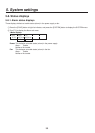
When the AW-HE100N/E is to be connected to the unit, select a setting which will enable operations to be
controlled by the controller in the “Controller” item of the AW-HE100N/E’s pan-tilt head unit setting menu
( Pan Tilt Head Setting ).
For further details, refer to the Operating Instructions of the AW-HE100N/E.