


9-7
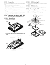
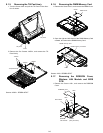
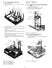
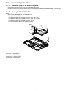
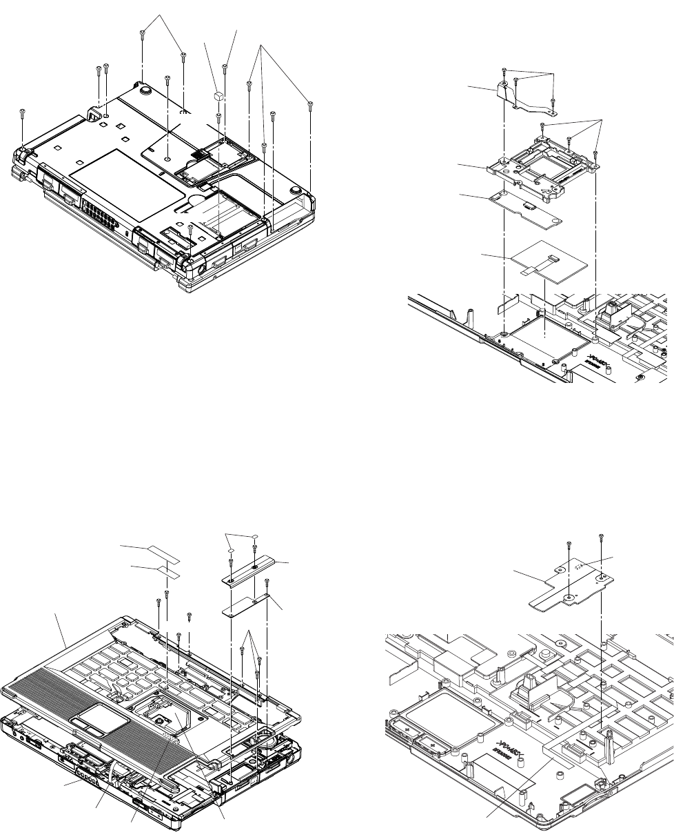
9.1.14. Removing the Top Cover
1. Remove the Gasket.
2. Remove the Screws <N2>, <N4>, <N9> and ten Screws
<N14>
3. Turn the unit to the face, remove the Screw <N12> and
five Screws <N8>.
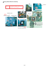
4. Remove the WP Sheet and Tape, and remove the Screw
<N12>.
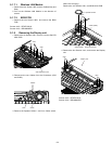
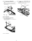
5. Remove the two Screw Sheets.
Remove the two Screws <N9>, and remove the Cover
BT.
Remove the Screw <N2> and disconnect the Cable from
the BT UNIT PCB, and remove it.
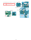
6. Disconnect the FFC and KBD FPC from the Connec-
tors(CN23 and CN22), and lift up the Top Cover Ass’y and
remove it.
Screws <N2> : DFHE5122YA
Screw <N4> : DRHM0093ZA
Screws <N8> : DRHM5054XAT
Screws <N9> : DRHM5104ZAT
Screws <N12> : DXSB2+4FNLT
Screws <N14> : XTB26+10GJKT
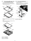
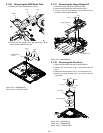
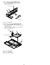
9.1.15. Removing the Pad and TOUCH PAD
PCB
1. Remove the six Screws <N12>.
2. Remove the Top Relay Plate and Pad Holder.
3. Remove the Pad and TOUCH PAD PCB.
Screws <N12> : DXSB2+4FNLT
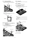
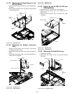
9.1.16. Removing the SD PCB
1. Remove the two Screws <N12>.
2. Disconnect the FFC from the Connector(CN4300), and
remove the SD PCB.
Screws <N12> : DXSB2+4FNLT
<N14>
<N2>
<N14>
<N14>
<N4>
Gasket
<N9>
<N14>
<N14>
<N14>
<N14>
Screw
sheet
Cover
BT
BT UNIT
PCB
CN22
KBD FPC
CN23
FFC
<N9>
WP sheet
Tape
<N9>
<N2>
<N2>
<N8>
Top cover ass'y
<N8>
<N12>
<N8>
Top relay plate
Pad holder
TOUCH PAD
PCB
Pad
<N12>
<N12>
<N12>
SD PCB
FFC
<N12>
CN4300