


9-40
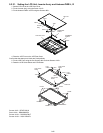
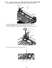
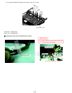
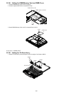
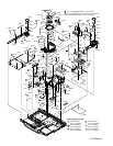
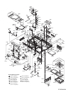
■Arranging the Speaker Cables when assembling the SW LED MDC PCB.
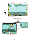
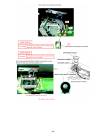
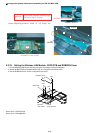
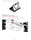
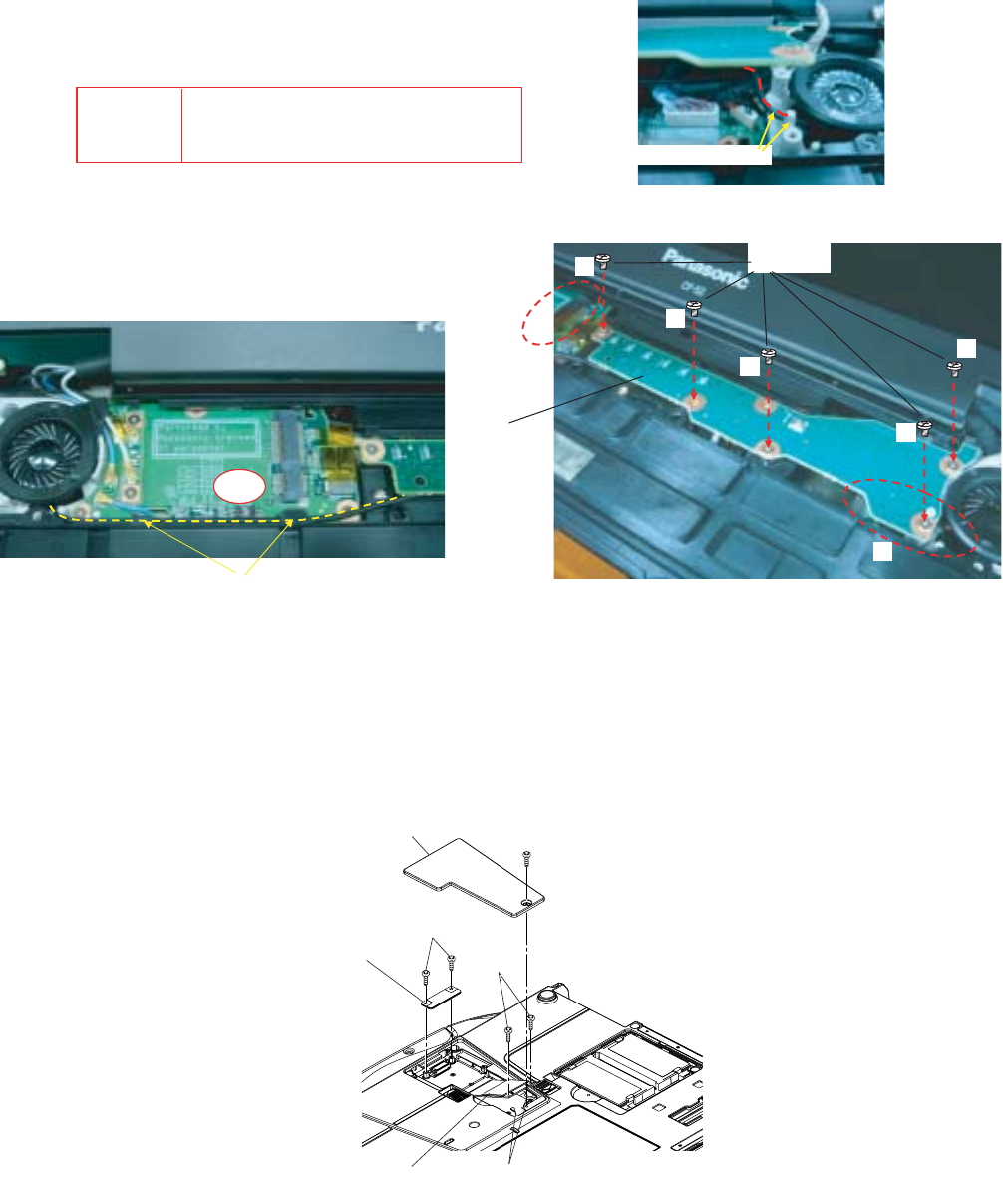
9.2.23. Setting the Wireless LAN Module, BIOS PCB and ROBSON Cover
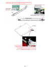
1. Put the Wireless LAN Module into the connector at an angle of fourty-five degrees.
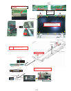
2. Attach the BIOS PCB to the MAIN HIGH PCB, fix it using the two Screws <N2>.
3. Set the ROBSON Cover, and fix it using the Screw <N3>.
Screw <N2> : DFHE5122YA
Screw <N3> : DRHM0065ZA
Torque of tightening screw:0.2 0.02N m( 2.0 0.2kgf cm)
CAUTION
S1:Insulation S2:Bitten S3:Sharp Edge
S4:Part No. Check S5:Other
S2
PWB SW
SCREW
SP CABLE R is on the post.
SP CABLE is under of PWB.
Detailed of portion B
Detailed of portion A
<N2>
<N2>
Wireless
LAN module
Cables
(Gray and blue)
ROBSON cover
<N3>
BIOS PCB