9-32
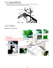
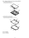
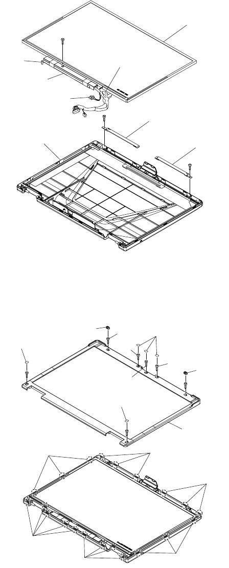
9.2.21. Setting the LCD Unit, Inverter Ass’y and Antenna PWB L, R
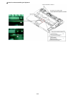
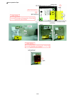
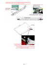
1. Set the LCD Unit to the LCD Rear Cover
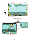
2. Fix the Inverter Ass’y using the Screw <N12>.
3. Fix the Anttena PWB L and R using the Screws <N2>.
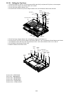
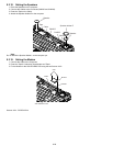
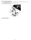
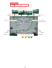
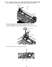
4. Place the LCD Front on the LCD Rear Case.
Confirm that the twenty-one Hooks are fixed perfectly.
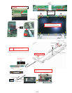
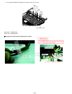
5. Fix the LCD Front using the five Screws <N4> and two Screws <N15>.
6. Paste the LCD Screw Sheet and LCD Rubber.
Screws <N2> : DFHE5122YA
Screw <N4> : DRHM0093ZA
Screws <N12> : DXSB2+4FNLT
Screws <N15> : XQN17+BJ6FJ
<N12>
Cable
Inverter
ass'y
Cable
<N2>
Tape
<N2>
LCD rear cover
ANTENNA
PWB R
LCD unit
ANTENNA
PWB L
<N15>
<N15>
<N4>
<N4>
LCD
rubber
LCD
rubber
LCD screw
sheet
LCD screw
sheet
LCD screw
sheet
<N4>
<N4>
<N4>
Hooks
Hooks
Hooks
Hooks
Hooks
LCD front
Hooks


