


205
[Reference]
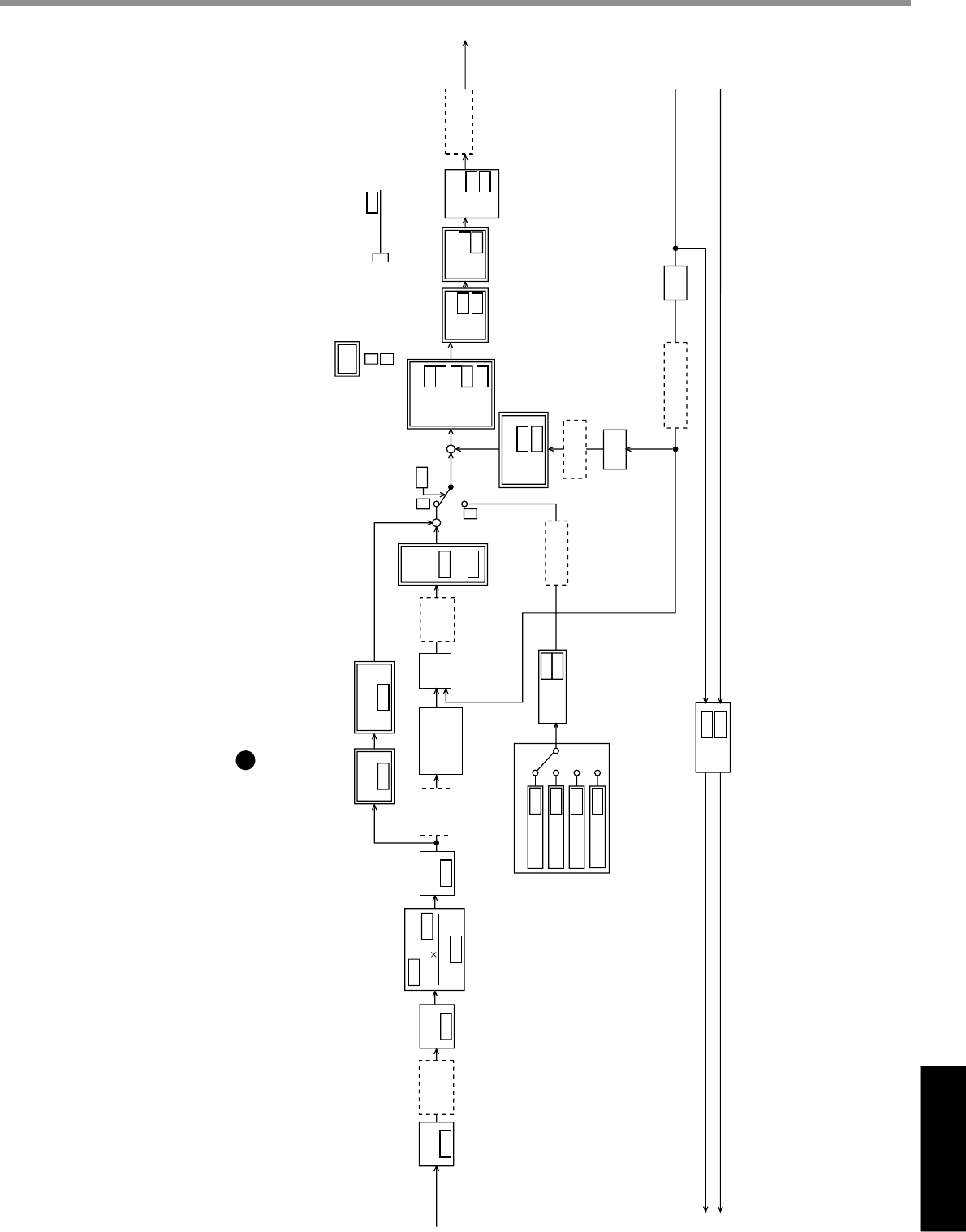
Reference
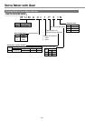
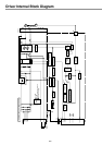
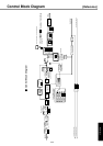
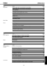
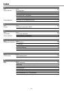
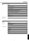
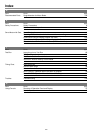
Control Block Diagram
Pulse Row
Command
PULS
SIGN
Encoder Signal
(Phases A/B)
Encoder Signal (Phase Z)
+
+
+
+
-
-
Input Mode
Setting
Frequency Pr2B
Setting of Filter Pr2C
Smoothing
Filter
Pr4C
FIR Filter
Pr4E
Pr18
1st
Position
Pr10
Deviation
Counter
2nd Pr1B
1st
Pr13
Speed Detection
Filter
Width
Pr1E
Frequency
Pr1D
Pr02
Select with
Notch Filter
Pr5E
Torque Limit
PANATERM
Torque
Command
Pr1C
1st
Pr71
2nd
Pr14
Torque
Command Filter
Selection of Control Mode
Velocity Feed
Forward
Pr15
Feed Forward
Filter
Pr16
Pr42
Pr53
Pr54
Pr59
Pr58
Pr55
Pr56
Pr44
Internal 1st
Speed
Speed Setting Internal/
External Switching
Between Acceleration and Deceleration
Dividing
Pr45
Inversion
4 times
Multiplier
Speed
Detection
P
S
P
: Internal Velocity
Control Mode
: Position Control Mode
: Servo Gain/Filter Time Constant Related Block
S
Pr02
Denominator
Pr46
Pr4B
Numerator
Scale
Pr4A
Numerator
2
Command Dividing/
Multiplier
Acceleration
Deceleration
Pr19
Pr1A
Pr11
Pr12
Pr20
1st Speed
1st
ntegration
Speed Error
Driver
PANATERM
Monitor
Total of
Command
ulses
PANATERM Monitor
Feedback Pulse
PANATERM
Waveform Graphic
Actual Speed
PANATERM
Velocity Control Mode
Waveform
Graphic
Command
Speed
Waveform
Graphic
Position
Deviation
PANATERM
Position Control Mode
Vibration Damping
Filter
PANATERM
Position Control Mode
Position
Error
Driver
2nd
Position
Waveform Graphic
Command Speed
2nd
Speed
2nd
ntegration
Inertia Ratio
Internal 2nd
Speed
Internal 3rd
Speed
Internal 4th
Speed
Waveform Graphic
Torque Command
1st
2nd
Feedback Pulse (OA•OB)
Feedback Pulse (OZ•CZ)
Control Block Diagram