Chapter 4 Settings — [ADVANCED MENU] menu
ENGLISH - 61
19) Press as to select an item, and press qw to adjust the setting.
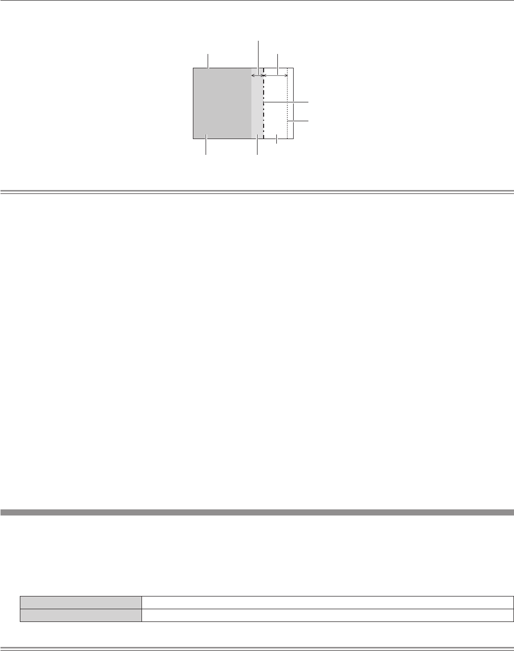
[BLACK BORDER WIDTH] (Right)
Projection range Edge blending [WIDTH] (Right)
[MARKER] (Red)
Edge blending [START] (Right)
([MARKER] (Green))
[BLACK BORDER LEVEL]
[NON-OVERLAPPED BLACK LEVEL]
[NON-OVERLAPPED BLACK LEVEL]
Note
f [BRIGHTNESS ADJUST] is a function that makes the increased brightness in black level of the overlapping image area difcult to notice
when [EDGE BLENDING] is used to congure multiple screens. The optimal point of correction is set by adjusting [NON-OVERLAPPED
BLACK LEVEL] so the black level of the overlapping image area will be the same level as the non-overlapping area. If the border area of the
part where the image is overlapping and the non-overlapping part gets brighter after adjusting [NON-OVERLAPPED BLACK LEVEL], adjust
the width of the top, bottom, left, or right. Adjust [BLACK BORDER LEVEL] when the width adjustment makes only the border area darker.
f The joining part may look discontinuous depending on the position you are looking from when a screen with high gain or rear screen is used.
f When conguring multiple screens using both horizontal and vertical edge blending, adjust [OVERLAPPED BLACK LEVEL] rst before
making adjustments in Step 12). Adjustment method is same as the procedure of [NON-OVERLAPPED BLACK LEVEL].
f If only horizontal or vertical edge blending is used, set all items in [OVERLAPPED BLACK LEVEL] to 0.
f [AUTO TESTPATTERN] settings change together with the [AUTO TESTPATTERN] of [COLOR MATCHING].
f Depending on the resolution of the signal to be input, the line width of the marker is changed.
f When an interlaced signal is input or [NOISE REDUCTION] is set to [ON], the marker color may look pale.
f The [EDGE BLENDING] setting is not reected in the internal test pattern.
f [EDGE BLENDING] cannot be selected if a signal is not being input.
f When using the edge blending function, inputting the signal of same resolution as DLP chips is recommended.
f The [EDGE BLENDING] setting is disabled when viewing 3D images.
f [EDGE BLENDING] cannot be selected when the VIDEO input is selected.
f When [PICTURE MODE] is set to [DYNAMIC], [EDGE BLENDING] cannot be selected.
f When [EDGE BLENDING] is set to [ON] while [NATURAL] is selected in [PICTURE MODE], the image may not be compliant to sRGB.
f When [EDGE BLENDING] is set to [ON] while [REC709] is selected in [PICTURE MODE], the image may not be compliant to Rec.709.
f When [EDGE BLENDING] is set to [ON] while [DICOM SIM.] is selected in [PICTURE MODE], the appearance of images may be different
from DICOM standards.
f The following menu items cannot be selected when the edge blending function is in use.
g [AUTO] in [DAYLIGHT VIEW] (x page 52)
g [ECO SAVE1] and [ECO SAVE2] in [LIGHT POWER] (x page 77)
f The [AMBIENT LIGHT DETECTION] setting in [AUTO POWER SAVE] (x page 78) is disabled when the edge blending function is in use.
f For some interlaced signals, edge blending may not be adjusted appropriately.
f Depending on the settings of starting position and correction width of edge blending, the setting values of [START] and [WIDTH] may be
automatically changed from original values when the image size is reduced using [ASPECT] or [ZOOM].
[FRAME RESPONSE]
If 1 080/60i, 1 080/50i, or 1 080/24sF signals are input, the video frame delay can be shortened by simplifying video processing.
1) Press as to select [FRAME RESPONSE].
2) Press qw to switch [FRAME RESPONSE].
f The items will switch each time you press the button.
[NORMAL] Sets a priority on image quality.
[FAST] Sets a limit to the time delay.
Note
f Selecting [NORMAL] allows images to be viewed in higher quality.
f If the [NOISE REDUCTION] setting is [ON], [FRAME RESPONSE] cannot be set.
f [FRAME RESPONSE] cannot be set when viewing 3D videos.


