3160-A2-GB21-90 February 2001
D-1
D
Pin Assignments
Overview
The DSU/CSU is shipped with a power module and a VF cable. Various other
interconnecting cables are available. For cable feature numbers, refer to
Appendix I,
Equipment List
. This appendix describes connector pin assignments
and cables.
T1 Network Interface
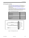
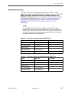
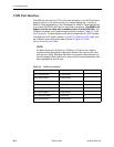
The T1 network interface connector is an RJ48C, 8-position, unkeyed modular jack
(Table D-1, T1 Network Interface Connector).
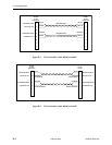
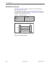
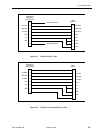
The T1 line interface cable is a 20-foot, 24 AWG solid, 2-twisted pair cable that is
either RJ48C-to-RJ48C (Figure D-1, T1 Line Interface Cable, RJ48C-to-RJ48C) or
RJ48C-to-DA15P (Figure D-2, T1 Line Interface Cable, RJ48C-to-DA15P).
Table D-1. T1 Network Interface Connector
Signal Pin Number
Receive Ring 1
Receive Tip 2
Transmit Ring 4
Transmit Tip 5


